Home
› 240V Pid Controller Wiring Diagram / Temperature Controller High Precision All Intelligent Pid Digital Thermostat Temperature Control Switch Rex C900 Universal Input Input Input Switch Aliexpress / Wiring diagram furthermore turn signal wiring diag.
240V Pid Controller Wiring Diagram / Temperature Controller High Precision All Intelligent Pid Digital Thermostat Temperature Control Switch Rex C900 Universal Input Input Input Switch Aliexpress / Wiring diagram furthermore turn signal wiring diag.
240V Pid Controller Wiring Diagram / Temperature Controller High Precision All Intelligent Pid Digital Thermostat Temperature Control Switch Rex C900 Universal Input Input Input Switch Aliexpress / Wiring diagram furthermore turn signal wiring diag.. Let me assume a suitable mathematical model for the plant and then go ahead. In many control tasks, the classic pid controller that influences the process is not the sole important element but great demands are also made on signal 2.1 general information. A close loop system is also known as feedback control system and this type of system is used to design automatically stable system at desired output or. Pid schematic wiring diagram database. A pid controller is an intelligent device that learns and trains itself to the behaviour of a system so as to not overshoot or undershoot the target temperature.
Rev 1.27 2 www.temcoline.net t50 user's manual warning 1. Panel cutout 3.1 insert temperature controller into the mounting hole in the panel, then put on the fixer from the rear 7.2 control the load via external contactor. Don't touch ac power wiring terminals when controller has been powered! Operation levels 7.1 levels diagram level 1 (user level) press key 5 seconds lck = 0000 press key+ 5 seconds press key 5 seconds level 2 (pid level). Gm steering column wiring diagram.
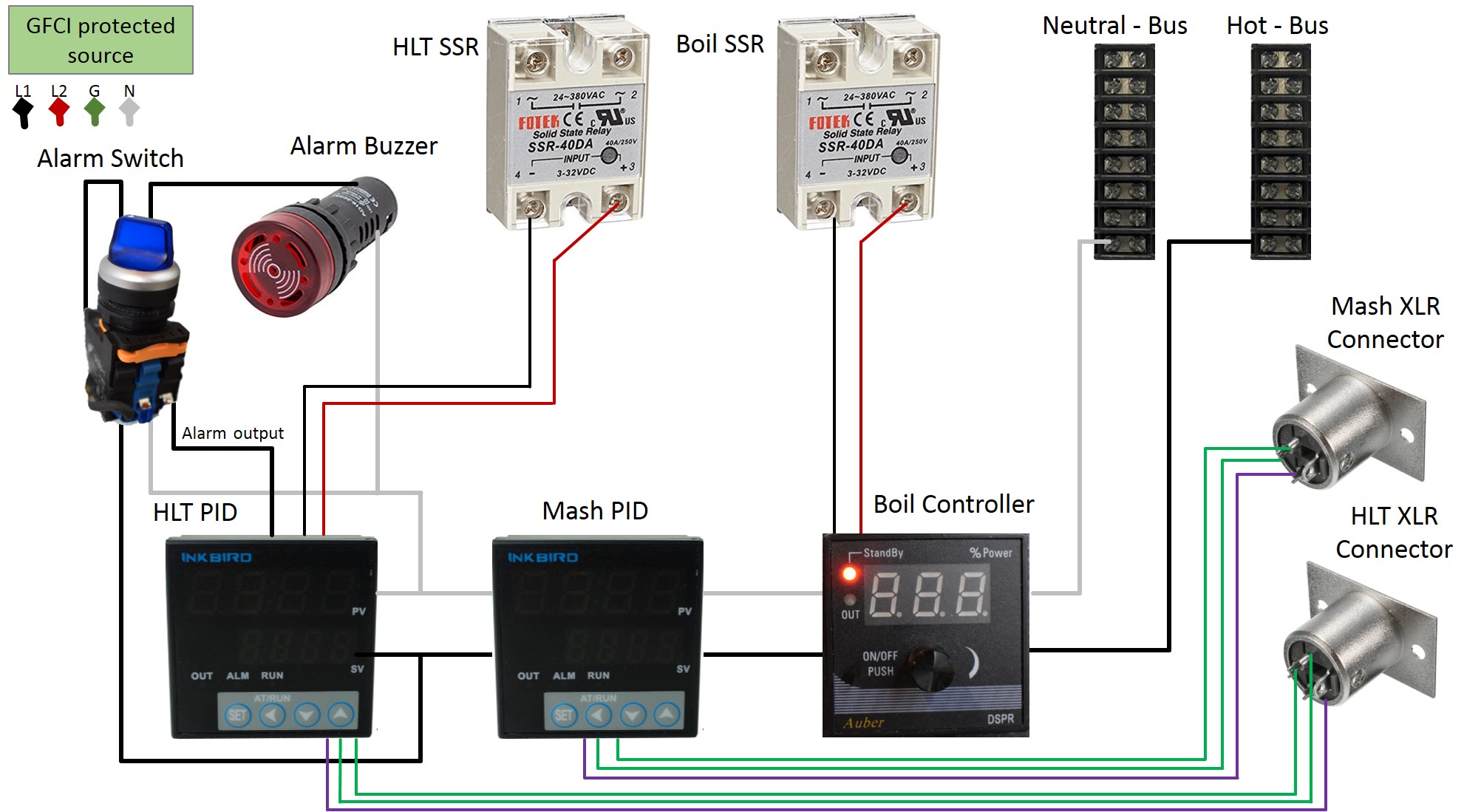
How To Build A Brewing Control Panel Herms 240v 30 Amp Skrilnetz from skrilnetz.net Before explaining pid controller, let's revise about control system. This post is bout arduino and pid based dc motor position control, arduino control position of dc motor using pid calculation close loop system. Pid schematic wiring diagram database. Pid is the part of programming, on which a complex calculation carried out by controller and manipulate do the wiring as shown in the image above. Conventions used with parameter and block names in the block diagrams. Build your controller in a housing designed for electrical wiring. Again on the diagram there is another 3 way connection between ssr output, pid and power cord. Pid temperature controller wiring diagram schemati.
Before explaining pid controller, let's revise about control system.
The matlab code is provided at the end of this article. Keep the power off until all of the wirings are completed! Architectural wiring diagrams appear in the approximate locations and interconnections of receptacles, lighting, and permanent electrical facilities in a building. These wiring diagrams are provided as a free resource to the homebrewing community. Pid diagram newest arduino pid temperature controller free diagram. I am in uk, voltage is 240v in house, i guess as the power went off on both attempts (in garage socket and house socket) the power in the garage. 2006 ford explorer fuse panel diagram. Super simple pid controller build/wiring | aussie home brewer trolled around a bit, but couldn't find any simple wiring here's the keg king one: As you see in block diagram of pid controller, the error essentially goes through each pid block and their outputs are summed up and form a control signal that drives the process to the desired setpoint. Safety requirements for permanently connected. This channel is designed to offer insight and background on the science, art and practice of making alcohol based products at home.major parts list:pid. Again on the diagram there is another 3 way connection between ssr output, pid and power cord. Don't touch ac power wiring terminals when controller has been powered!
Keep the power off until all of the wirings are completed! The names of the parameters are a maximum of. Generating a control pwm signal from a pid controller. Click the register link above to proceed. Super simple pid controller build/wiring | aussie home brewer trolled around a bit, but couldn't find any simple wiring here's the keg king one:
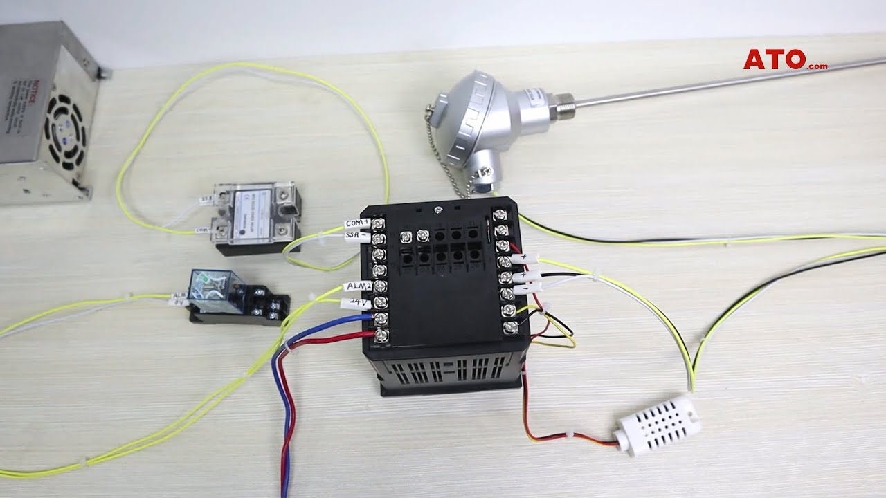
Pid Temperature Controller Multi Channel Ato Com from i.ytimg.com Implementing pid controller using arduino. A wiring diagram typically gives info regarding the relative placement as well as setup of devices as well as terminals on the tools, in order to help in building or servicing the gadget. In many control tasks, the classic pid controller that influences the process is not the sole important element but great demands are also made on signal 2.1 general information. Analog pid temperature controller circuit. Add a night light control. Generating a control pwm signal from a pid controller. Pid is the part of programming, on which a complex calculation carried out by controller and manipulate do the wiring as shown in the image above. As you see in block diagram of pid controller, the error essentially goes through each pid block and their outputs are summed up and form a control signal that drives the process to the desired setpoint.
Architectural wiring diagrams appear in the approximate locations and interconnections of receptacles, lighting, and permanent electrical facilities in a building.
Don't touch ac power wiring terminals when controller has been powered! So i simulated a pid controller in matlab. Interconnecting wire routes may be shown approximately, where particular receptacles or fixtures. This channel is designed to offer insight and background on the science, art and practice of making alcohol based products at home.major parts list:pid. Panel cutout 3.1 insert temperature controller into the mounting hole in the panel, then put on the fixer from the rear 7.2 control the load via external contactor. Keep the power off until all of the wirings are completed! Build your controller in a housing designed for electrical wiring. Analog pid temperature controller circuit. Architectural wiring diagrams appear in the approximate locations and interconnections of receptacles, lighting, and permanent electrical facilities in a building. 2006 ford explorer fuse panel diagram. A pid controller is an intelligent device that learns and trains itself to the behaviour of a system so as to not overshoot or undershoot the target temperature. When the relay contact is open, or the triac is off, the snubber circuit passes 0.6ma at 110vac and 1.2ma at 240vac. A pid controller consists of a proportional element, an integral element and a derivative element, all three connected in parallel.
Architectural wiring diagrams appear in the approximate locations and interconnections of receptacles, lighting, and permanent electrical facilities in a building. The matlab code is provided at the end of this article. The names of the parameters are a maximum of. When the relay contact is open, or the triac is off, the snubber circuit passes 0.6ma at 110vac and 1.2ma at 240vac. Pid temperature controller wiring diagram schemati.
Bd 4950 Diagram Of Pid Temperature Controller Wiring Likewise Arduino Pid Free Diagram from static-assets.imageservice.cloud I am in uk, voltage is 240v in house, i guess as the power went off on both attempts (in garage socket and house socket) the power in the garage. Again on the diagram there is another 3 way connection between ssr output, pid and power cord. For example, the maximum voltage that the lm317can works is 37 volts, and if in our diagram we take r9 as 240 ohms, then we do the calculation for r10. Implementing pid controller using arduino. A wiring diagram typically gives info regarding the relative placement as well as setup of devices as well as terminals on the tools, in order to help in building or servicing the gadget. 120vac will kill you just as fast and just as dead as 240vac will kill you. Pid schematic wiring diagram database. The matlab code is provided at the end of this article.
There are two types of systems;
Pid diagram newest arduino pid temperature controller free diagram. The matlab code is provided at the end of this article. The names of the parameters are a maximum of. Digital indicating controller (panel mounting type). Wire up the components as shown in the diagram below using the wire sizes and colours indicated. Conventions used with parameter and block names in the block diagrams. This channel is designed to offer insight and background on the science, art and practice of making alcohol based products at home.major parts list:pid. Click the register link above to proceed. So i simulated a pid controller in matlab. Operation levels 7.1 levels diagram level 1 (user level) press key 5 seconds lck = 0000 press key+ 5 seconds press key 5 seconds level 2 (pid level). Gm steering column wiring diagram. Pid temperature controller wiring diagram schemati. These wiring diagrams are provided as a free resource to the homebrewing community.