Home
› Psc Motor Wiring Diagram - Dc Reversing Switch Wire Diagram Strip Light Wiring Diagram Gear8 Acquadimenta It / You will be able to learn exactly when the tasks should be completed, that makes it much easier for you to correctly handle your time and efforts.
Psc Motor Wiring Diagram - Dc Reversing Switch Wire Diagram Strip Light Wiring Diagram Gear8 Acquadimenta It / You will be able to learn exactly when the tasks should be completed, that makes it much easier for you to correctly handle your time and efforts.
Psc Motor Wiring Diagram - Dc Reversing Switch Wire Diagram Strip Light Wiring Diagram Gear8 Acquadimenta It / You will be able to learn exactly when the tasks should be completed, that makes it much easier for you to correctly handle your time and efforts.. Come back with the new ecm motor, you disconnect the relay, remove the psc motor. And youtube videos on converting x/ecm motors to psc applications. Blower motor wiring diagram manual. Here is a simple wiring diagram for accomplishing this: The brown and blue wires to the ecm x13 motor were low voltage.
4 wire reversible psc motor with a triple pole double throw switch. Jan 1, here is a simple wiring diagram for accomplishing this: 4 wire reversible psc motor. 4 wire reversible psc motor. Upflow, downflow, and horizontal • blower section usable as an electric furnace
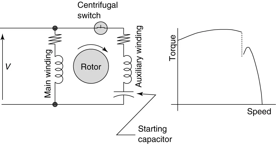
Types Of Single Phase Induction Motors Single Phase Induction Motor Wiring Diagram Electrical Academia from electricalacademia.com Since the single phase 2 wire circuit has no polarity, reversing only the incoming leads will not reverse the rotor's direction. It makes the process of building circuit simpler. Come back with the new ecm motor, you disconnect the relay, remove the psc motor. On the other hand, this diagram is a simplified variant of this arrangement. After a split phase or cap start motor is started, a centrifugal switch on the shaft opens, disconnecting the start winding or capacitor. Come back with the new ecm motor, you disconnect the relay, remove the psc motor. Blower motor wiring diagram manual. Dec 10, · david talks about basic compressor wiring.
Upflow, downflow, and horizontal • blower section usable as an electric furnace
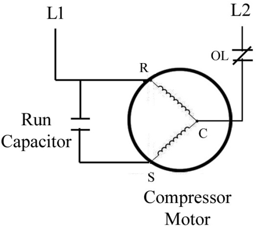
August 29, 2018 april 12, 2020. Isolate the compressor from the remainder of the circuit by disconnecting the As the capacitor is always in the circuit and thus this type of motor does not contain any starting switch. However, some people still struggle with the wiring part of the motor to the capacitor. It is also called as a single value capacitor motor. And youtube videos on converting x/ecm motors to psc applications. After a split phase or cap start motor is started, a centrifugal switch on the shaft opens, disconnecting the start winding or capacitor. Psc motor typical wiring diagram for a psc motor definition and characteristics. For groschopp 115 and 230 volt ac80, ac90, and ac100 single phase motors. 3 wire, 3 phase motor. Inst maint & wiring.qxd 5/03/2008 10:02 am page 6 The motor will now cycle with any call from the thermostat or control board. The brown and blue wires to the ecm x13 motor were low voltage.
Ac80, ac90, ac100 single phase motors; The brown and blue wires to the ecm x13 motor were low voltage. Ac65, ac80, ac90, ac100 three phase motors; (refer iring diagram.) the wiring related to the compressor motor and its starting circuit is identified. Always use wiring diagram supplied on motor nameplate.
Solved Draw A Sketch Of A Psc Hermetic Compressor With A Run Capa Chegg Com from media.cheggcdn.com Inst maint & wiring.qxd 5/03/2008 10:02 am page 6 Come back with the new ecm motor, you disconnect the relay, remove the psc motor. 4 wire reversible psc motor with a triple pole double throw switch. Schematic shows cw rotation facing the drive end. Come back with the new ecm motor, you disconnect the relay, remove the psc motor. The motor will now cycle with any call from the thermostat or control board. The motor then runs using only the run winding. Replacement of original wires must be with.
The motor then runs using only the run winding.
Refer to the motor manufacturer's data on the motor for wiring diagrams on standard frame ex e, ex d etc. Ac80, ac90, ac single phase motors; 3 wire, 3 phase motor. See the simplified circuit diagram on the following page. Cted to the compressor motor windings and start circuit. The brown and blue wires to the ecm x13 motor were low voltage. Wiring diagram capacitor psc motor. I replace the x13 blower motor model # 5sme39hxl with a psc motor operating a pcm every two years in your electrical bill compared to. However, some people still struggle with the wiring part of the motor to the capacitor. After a split phase or cap start motor is started, a centrifugal switch on the shaft opens, disconnecting the start winding or capacitor. S bharadwaj reddyaugust 1, 2017october 5, 2018. As the capacitor is always in the circuit and thus this type of motor does not contain any starting switch. It makes the process of building circuit simpler.
Jan 2, a wiring diagram for a psc motor is just going to utilize a high volt. Come back with the new ecm motor, you disconnect the relay, remove the psc motor. When installing heater kit, ensure speed tap does not exceed minimum blower speed (mbs) specified for the airhandler/heater kit combination on this unit's. Dec 10, · david talks about basic compressor wiring. Blower motor wiring diagram manual.
Know Your Potential Starting Relays from www.achrnews.com Here is a simple wiring diagram for accomplishing this: I replace the x13 blower motor model # 5sme39hxl with a psc motor operating a pcm every two years in your electrical bill compared to. Wiring diagrams for groschopp's ac single and three phase motors. Refer to the motor manufacturer's data on the motor for wiring diagrams on standard frame ex e, ex d etc. And youtube videos on converting x/ecm motors to psc applications. Ac80, ac90, ac single phase motors; As the capacitor is always in the circuit and thus this type of motor does not contain any starting switch. August 29, 2018 april 12, 2020.
You will be able to learn exactly when the tasks should be completed, that makes it much easier for you to correctly handle your time and efforts.
The brown and blue wires to the ecm x13 motor were low voltage. As the capacitor is always in the circuit and thus this type of motor does not contain any starting switch. Sep 22, ok , i measured the resistance of all combinations of the four wires. However, some people still struggle with the wiring part of the motor to the capacitor. The motor then runs using only the run winding. 4 wire reversible psc motor. Since the single phase 2 wire circuit has no polarity, reversing only the incoming leads will not reverse the rotor's direction. Psc motor typical wiring diagram for a psc motor definition and characteristics. 4 wire reversible psc motor. Wiring diagram capacitor psc motor. (refer iring diagram.) the wiring related to the compressor motor and its starting circuit is identified. Isolate the compressor from the remainder of the circuit by disconnecting the The motor will now cycle with any call from the thermostat or control board.