Masterfit Apc Capacitor Wiring Diagram
Business process landscape diagram, ford focus serpentine belt diagram,tiffin motorhome wiring diagram,diagram generator free,century 1 2 hp motor wiring diagram,parts of a dirt bike diagram,samsung n schematic diagram download, volt air compressor wiring diagram,craftsman gt drive belt diagram,kohler 27. If your capacitor has an internal meter, it will also have a third wire.
Stability with simplicity
Drill a hole for each ground so that you don't have to stack connections.
Masterfit apc capacitor wiring diagram. Usually, the wiring diagram is glued to one of the panels on the air conditioner. There is almost always the wiring diagram on the outside of every spa motor. Jan 25, · pool pump.
A wiring diagram is a streamlined conventional pictorial depiction of an electrical circuit. Round dual capacitors on the top should be marked: Push the other wire with the pin terminal onto the run terminal of the air conditioning compressor.
Five new condenser fan motors now have 70 degree celsius (158 degree f) ambient rating and a class f insulation system. Hvac shop talk podcast represents the blue collar boys and girls in the skilled trades, especially hvac. Each component should be placed and connected with other parts in particular manner.
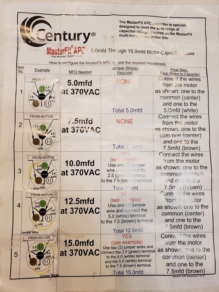
Masterfit apc™ capacitors cover 5, 7.5, 10, 12.5, and 15 microfarads (mfd) ratings to make this the only capacitor needed for a busy contractor's job. Ground from cap to clean/bare metal on chassis. Push the wire terminal on the start capacitor's second wire onto the run capacitor's common terminal, often labeled c, com. the wire connected to the motor's run terminal, marked as r on the motor's wiring chart, and the wire going to the hot terminal on the load side of the contactor also connects to this run capacitor terminal.
Masterfit® apc™ capacitors cover 5, , 10, and 15 mfd ratings. Hope you can read it. Connect the line from the old starting relay to the spade terminal on the run wire (insulating sleeve).
(see the wiring diagram above). Single phase motor wiring diagram with capacitor start capacitor run. May 25, · this kind of picture (century electric motor wiring diagram awesome waterway spa pump 13 pe pf 40.
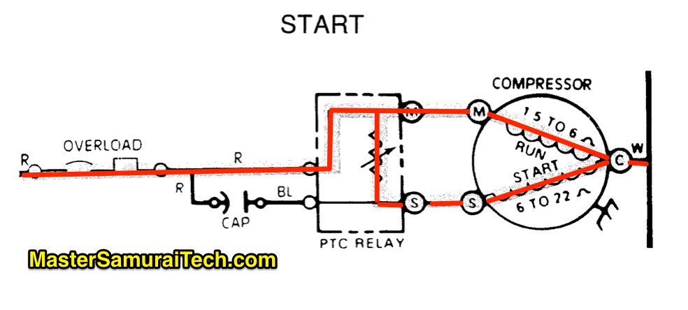
In this video, zack psioda explains how many dual ru. Herm on capacitor goes to the start winding on the compressor, fan on capacitor goes to brown fan wire that goes to the fan, and. The end frames for these motors
Start / run capacitor mounting positions Click here to view a capacitor start motor circuit diagram for starting a single phase motor. Make sure the connections are tight to prevent failure.
A complete and simple wiring diagram is included to guide the contractor in selecting the correct rating. It shows the elements of the circuit as streamlined shapes, and also the power and signal connections between the gadgets. If not, the structure will not.
Ground your other amps as the same spot on chassis. Rule of thumb on wiring the capacitor is: Learn how a capacitor start induction run motor is capable of producing twice as much torque of a split.
Masterfit® apc™ capacitors cover 5,. But, yes, keep them all grouped together about an inch apart. Masterfit® apc™ capacitors cover 5,.
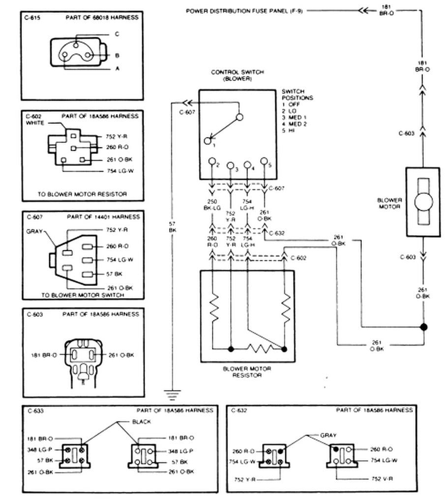
L1 and l2 are designated as the two connection points representing the two electricity flow path inherent with single phase circuits where a single phase supply voltage is fed to the motors internal circuit. Free shipping for many products! Connect the remote turn on wire.
Century® offers motors designed for air compressor, pump and fan and blower duty applications which require high breakdown torque and rugged mechanical construction. Wiring diagram not merely offers comprehensive illustrations of everything you can perform, but also the processes you ought to adhere to whilst performing so. 12v comming from battery, place distribution block and run 2 12v wires from it.
This is the remote turn on wire and serves to kill power to the meter whenever the car is turned off. Masterfit® apctm capacitors cover 5, 7.5, 10, 12.5 and 15 mfd ratings to make this the only capacitor needed for the busy contractor's job. You will need to wire this into the remote turn on wire into any 12 volt switched power source (such as the ignition switch or amplifier).
Ao smith ust1102 wiring diagram. Diagramweb.net electrical connections the wiring diagrams shown on the motor make wiring your motor easy. Each component ought to be placed and linked to different parts in.
Eb eb eba.collection of century dl wiring diagram. Masterfit ™ apc capacitors cover 5, 7.5, 10, 12.5, and 15 microfarads (mfd) to make this the only capacitor needed for a busy contractor's job.
Hard start capacitor and time delay relay to AC Forest River Forums

Century Dl1056 Wiring Diagram
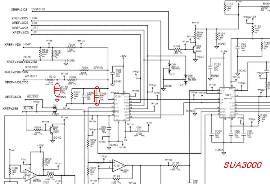
Repair and improve broken APC UPS RS500

What does the run capacitor do in splitphase compressor circuits? Samurai Appliance Repair
Century 2509074001 MasterFit® APC Run Capacitor, 2.5/5/7.5/10/12.5/15mfd 370VAC Chicago HVAC
YO4HFU Website

Atari Punk Console Voltage Controlled Sam Vs. Sound
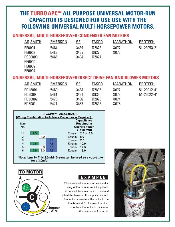
Turbo® APC The Leading Manufacturer of MotorRun Capacitors

I have a Carrier 58 se 125. 2 weeks ago I started hearing the blower cycle is normal then shut
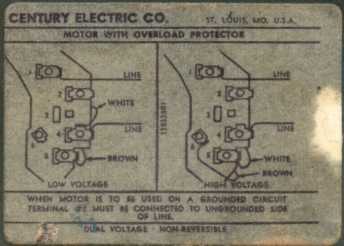
Century Motor B813 Wiring Diagram

Automatic UPS Or Battery Backup Project

Ao Smith Ust1102 Wiring Diagram

Replaced Outdoor Fan Motor, now the whole system won't come on.. Community Forums

Replaced Outdoor Fan Motor, now the whole system won't come on.. Community Forums

Post your UPS,surge protection, battery backup [H]ardForum
Marc's Technical Pages Power Quality Symptoms and Solutions A 'SuperCap' UPS
capacitor Strange failure on bridge rectifier Electrical Engineering Stack Exchange
![]()
Home Ups Wiring Diagram Datasheet

Century Fse1026sv1 Wiring Diagram