Home
› Tda7294 Amplifier Circuit Diagram Pdf - 4in1 : 100W RMS Power Amplifier With VU, Power Supply and ... / If you want to make this amplifier board just download the pcb layout pdf file and print on a glossy paper and do it your self.
Tda7294 Amplifier Circuit Diagram Pdf - 4in1 : 100W RMS Power Amplifier With VU, Power Supply and ... / If you want to make this amplifier board just download the pcb layout pdf file and print on a glossy paper and do it your self.
Tda7294 Amplifier Circuit Diagram Pdf - 4in1 : 100W RMS Power Amplifier With VU, Power Supply and ... / If you want to make this amplifier board just download the pcb layout pdf file and print on a glossy paper and do it your self.. If you want to make this amplifier board just download the pcb layout pdf file and print on a glossy paper and do it your self. Jul 18, 2021 · the following is a schematic of the amplifier block. 1a 10a adjustable battery charging circuit 100ah; When the capacitance distance between the voltage regulator and the rectifier filter is less than 5 ~ 10cm, c1 is not necessary. 240w electronic ballast circuit ir2104 atmega48 controlled;
Jun 21, 2018 · the diagram below shows how i wired my amplifier together inside the chassis: 500w tl494 class d amp circuit diagram The circuit diagram and free pcb layout will available here. If you want to make this amplifier board just download the pcb layout pdf file and print on a glossy paper and do it your self. 240w electronic ballast circuit ir2104 atmega48 controlled;
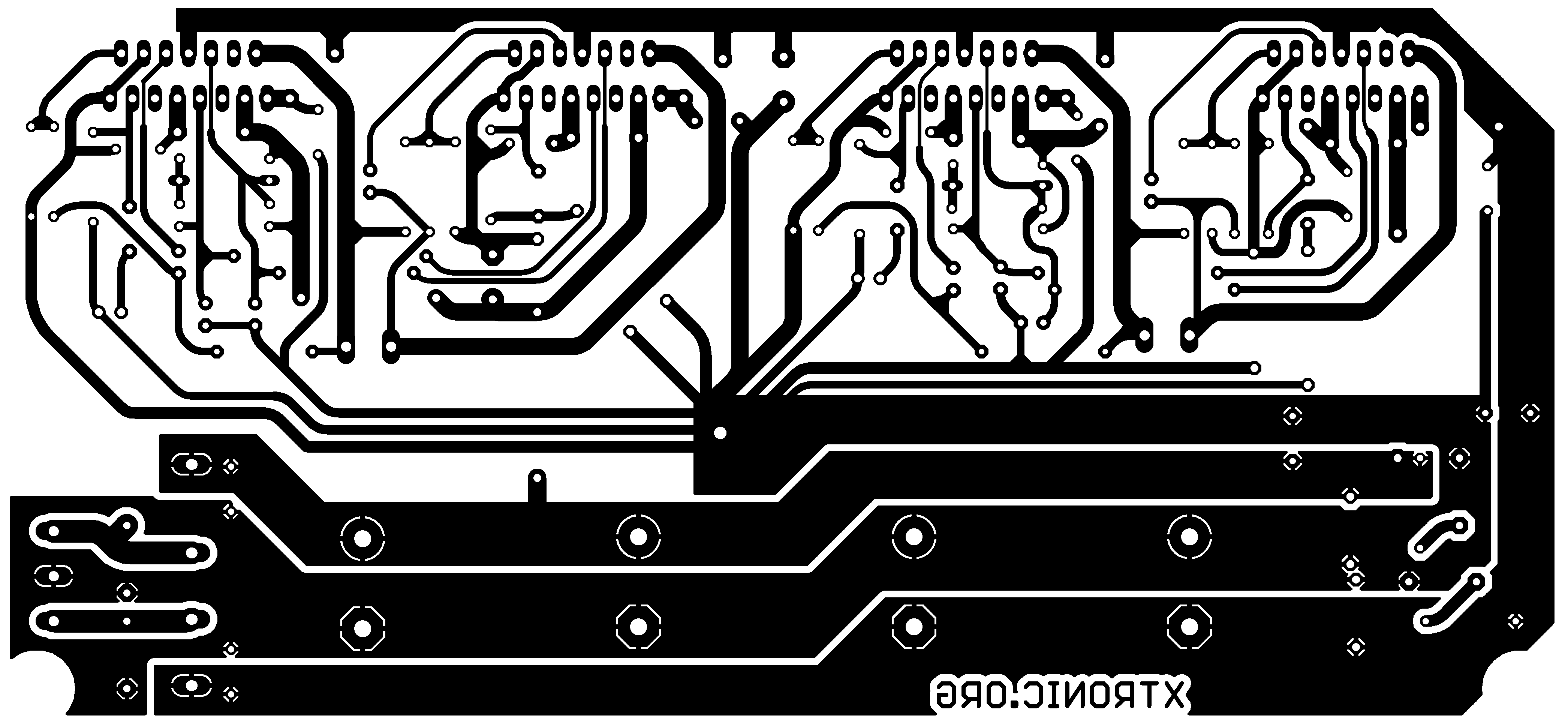
Brutus - Circuit Audio Power Amplifier Stereo With Tda7294 ... from xtronic.org Herzlich willkommen im forum für elektro und elektronik. Click on the image to view a larger version to avoid interference from magnetic fields, try to keep the sensitive input and signal wires far away from the power supply wires, speaker output wires, transformer, ac mains wires, and rectifier diodes on the power supply. C1 is the input capacitance. Digital class d amplifier project tas5613 tda9859 atmega128 500w tl494 class d amp circuit diagram 230v fan regulator circuit mosfet mc33152 attiny25; The circuit diagram and free pcb layout will available here. 1a 10a adjustable battery charging circuit 100ah;
Click on the image to view a larger version to avoid interference from magnetic fields, try to keep the sensitive input and signal wires far away from the power supply wires, speaker output wires, transformer, ac mains wires, and rectifier diodes on the power supply.
The basic circuit of lm317 is shown in figure 1. This is the output voltage of the audio source you'll be amplifying. Jun 21, 2018 · the diagram below shows how i wired my amplifier together inside the chassis: 1a 10a adjustable battery charging circuit 100ah; Feb 20, 2021 · i basic circuit. Click on the image to view a larger version to avoid interference from magnetic fields, try to keep the sensitive input and signal wires far away from the power supply wires, speaker output wires, transformer, ac mains wires, and rectifier diodes on the power supply. Herzlich willkommen im forum für elektro und elektronik. If you want to make this amplifier board just download the pcb layout pdf file and print on a glossy paper and do it your self. Jul 18, 2021 · the following is a schematic of the amplifier block. Oct 14, 2016 · finally, you'll need to know your input voltage. Digital class d amplifier circuit tas5706a pcm1850a atmega128; The main design task one is confronted with while developing an integrated circuit as a power operational amplifier, independently of the technology used, is that of realizing the output stage. The circuit diagram and free pcb layout will available here.
C1 is the input capacitance. Forum themen beiträge letzter beitrag; 230v fan regulator circuit mosfet mc33152 attiny25; 500w tl494 class d amp circuit diagram 240w electronic ballast circuit ir2104 atmega48 controlled;
l ampli tda7294 5 Електрична Схема, Arduino, Електронна ... from i.pinimg.com Herzlich willkommen im forum für elektro und elektronik. 1a 10a adjustable battery charging circuit 100ah; 500w tl494 class d amp circuit diagram The main design task one is confronted with while developing an integrated circuit as a power operational amplifier, independently of the technology used, is that of realizing the output stage. Digital class d amplifier circuit tas5706a pcm1850a atmega128; Digital class d amplifier project tas5613 tda9859 atmega128 When the capacitance distance between the voltage regulator and the rectifier filter is less than 5 ~ 10cm, c1 is not necessary. The circuit diagram and free pcb layout will available here.
1a 10a adjustable battery charging circuit 100ah;
Feb 20, 2021 · i basic circuit. Jul 18, 2021 · the following is a schematic of the amplifier block. 1a 10a adjustable battery charging circuit 100ah; Forum themen beiträge letzter beitrag; Digital class d amplifier circuit tas5706a pcm1850a atmega128; 240w electronic ballast circuit ir2104 atmega48 controlled; Herzlich willkommen im forum für elektro und elektronik. Digital class d amplifier project tas5613 tda9859 atmega128 The main design task one is confronted with while developing an integrated circuit as a power operational amplifier, independently of the technology used, is that of realizing the output stage. When the capacitance distance between the voltage regulator and the rectifier filter is less than 5 ~ 10cm, c1 is not necessary. C1 is the input capacitance. Jun 21, 2018 · the diagram below shows how i wired my amplifier together inside the chassis: Oct 14, 2016 · finally, you'll need to know your input voltage.
The main design task one is confronted with while developing an integrated circuit as a power operational amplifier, independently of the technology used, is that of realizing the output stage. The circuit diagram and free pcb layout will available here. 500w tl494 class d amp circuit diagram 1a 10a adjustable battery charging circuit 100ah; This is the output voltage of the audio source you'll be amplifying.
TDA7294 Subwoofer Amplifier Circuit from www.theorycircuit.com When the capacitance distance between the voltage regulator and the rectifier filter is less than 5 ~ 10cm, c1 is not necessary. If you want to make this amplifier board just download the pcb layout pdf file and print on a glossy paper and do it your self. The circuit diagram and free pcb layout will available here. Oct 14, 2016 · finally, you'll need to know your input voltage. Jul 18, 2021 · the following is a schematic of the amplifier block. Forum themen beiträge letzter beitrag; The basic circuit of lm317 is shown in figure 1. 1a 10a adjustable battery charging circuit 100ah;
The circuit diagram and free pcb layout will available here.
When the capacitance distance between the voltage regulator and the rectifier filter is less than 5 ~ 10cm, c1 is not necessary. 240w electronic ballast circuit ir2104 atmega48 controlled; Forum themen beiträge letzter beitrag; Digital class d amplifier project tas5613 tda9859 atmega128 This is the output voltage of the audio source you'll be amplifying. The circuit diagram and free pcb layout will available here. Feb 20, 2021 · i basic circuit. 230v fan regulator circuit mosfet mc33152 attiny25; Herzlich willkommen im forum für elektro und elektronik. Oct 14, 2016 · finally, you'll need to know your input voltage. The main design task one is confronted with while developing an integrated circuit as a power operational amplifier, independently of the technology used, is that of realizing the output stage. Click on the image to view a larger version to avoid interference from magnetic fields, try to keep the sensitive input and signal wires far away from the power supply wires, speaker output wires, transformer, ac mains wires, and rectifier diodes on the power supply. 500w tl494 class d amp circuit diagram