Home
› Wiring Connection Diagram - Wiring Diagram H Bridge Electrical Switches Circuit Diagram Electrical Wires Cable Png ... : Wiring diagrams can be helpful in many ways, including illustrated wire colors, showing where different elements of your project go using electrical symbols, and showing what wire goes where.
Wiring Connection Diagram - Wiring Diagram H Bridge Electrical Switches Circuit Diagram Electrical Wires Cable Png ... : Wiring diagrams can be helpful in many ways, including illustrated wire colors, showing where different elements of your project go using electrical symbols, and showing what wire goes where.
Wiring Connection Diagram - Wiring Diagram H Bridge Electrical Switches Circuit Diagram Electrical Wires Cable Png ... : Wiring diagrams can be helpful in many ways, including illustrated wire colors, showing where different elements of your project go using electrical symbols, and showing what wire goes where.. The 3 prong dryer wiring diagram here shows the proper connections for both ends of the circuit. See wiring diagram and/or tables 6 and 7 for wire size, fuse/circuit breaker size, and ground wire sizes. It is possible to run the drive via the digital operator without connecting digital i/o wiring. Multiple outlet in serie wiring diagram : Electrical contactor connection, contactor wiring diagram, contactor connection with thermal hey, in this article we are going to see proper electrical contactor connection and wiring diagram for.
D schematic pages do not contain component location d c numbers have been assigned for all electrical connectors. .house wiring connection electrical house wiring diagram software electrical house wiring drawing in wiring basic electrical house wiring diagram switch mcb rcb rcd uk eee eeestudy electric. Electrical schematic & wiring diagrams. Any break or malfunction in one outlet will cause all. Connect the drive and peripheral devices as shown in figure 3.1.
Diagram 1980 Yamaha Xj650 Wiring Diagram Full Version Hd Quality Wiring Diagram ... from chantaltorre.fr C numbers are listed in the location. Special libraries of highly detailed, accurate shapes and computer graphics, servers, hubs, switches, printers, mainframes, face plates, routers etc. Electrical schematic & wiring diagrams. A wiring diagram is a simplified conventional pictorial representation of an electrical circuit. For wiring in series, the terminal screws are the means for passing voltage from one receptacle to another. A wiring diagram is a simple visual representation of the physical connections and physical layout of an electrical system or circuit. Since wiring connections and terminal markings are shown, this type of diagram is helpful when wiring diagram. It is possible to run the drive via the digital operator without connecting digital i/o wiring.
Control unit on the actuator with plug.
Control unit on the actuator with plug. Apply quicksilver liquid neoprene to connection. .house wiring connection electrical house wiring diagram software electrical house wiring drawing in wiring basic electrical house wiring diagram switch mcb rcb rcd uk eee eeestudy electric. Any break or malfunction in one outlet will cause all. Electrical contactor connection, contactor wiring diagram, contactor connection with thermal hey, in this article we are going to see proper electrical contactor connection and wiring diagram for. Briggs & stratton supplies electrical components in addition to wiring diagrams, alternator identification information, alternator specifications and. Limit switch legend aov schematic (with block included) wiring (or connection) diagram wiring (or connection) diagram tray & conduit layout drawing embedded conduit drawing instrument loop. D schematic pages do not contain component location d c numbers have been assigned for all electrical connectors. Basic electrical home wiring diagrams & tutorials ups / inverter wiring diagrams & connection solar panel wiring & installation diagrams batteries wiring connections and diagrams single. This is the first method to make a as you see in the 2 way switch diagram below, you will find that the phase/live is connected with the. Special libraries of highly detailed, accurate shapes and computer graphics, servers, hubs, switches, printers, mainframes, face plates, routers etc. Now that you have a diagram or manual for your specific motherboard, you need to note some important info about motherboard wiring. It shows how the electrical wires are interconnected and can also show.
Basic electrical home wiring diagrams & tutorials ups / inverter wiring diagrams & connection solar panel wiring & installation diagrams batteries wiring connections and diagrams single. Control unit on the actuator with plug. .house wiring connection electrical house wiring diagram software electrical house wiring drawing in wiring basic electrical house wiring diagram switch mcb rcb rcd uk eee eeestudy electric. Connect the drive and peripheral devices as shown in figure 3.1. This post is about the voltmeter connection diagram, in this post you will learn about wiring connection of a dc voltmeter and ac voltmeter.
Diagram Fluorescent Wiring Diagram For Clock Full Version Hd Quality For Clock ... from wiringunlimitedsd.com A wiring diagram is a simplified conventional pictorial representation of an electrical circuit. Single voltage, wye connected, with partial current transformer protection, lightning arrestors & surge capacitors. See wiring diagram and/or tables 6 and 7 for wire size, fuse/circuit breaker size, and ground wire sizes. Any break or malfunction in one outlet will cause all. The 3 prong dryer wiring diagram here shows the proper connections for both ends of the circuit. Limit switch legend aov schematic (with block included) wiring (or connection) diagram wiring (or connection) diagram tray & conduit layout drawing embedded conduit drawing instrument loop. This is the first method to make a as you see in the 2 way switch diagram below, you will find that the phase/live is connected with the. A wiring diagram is a simple visual representation of the physical connections and physical layout of an electrical system or circuit.
Wiring diagrams can be helpful in many ways, including illustrated wire colors, showing where different elements of your project go using electrical symbols, and showing what wire goes where.
Connect the drive and peripheral devices as shown in figure 3.1. An ethernet cable connection for example, a connection diagram with two components shown using that then for autocad to generated the wiring diagram of an ethernet connection where the. Since wiring connections and terminal markings are shown, this type of diagram is helpful when wiring diagram. A wiring diagram is a simplified conventional pictorial representation of an electrical circuit. Limit switch legend aov schematic (with block included) wiring (or connection) diagram wiring (or connection) diagram tray & conduit layout drawing embedded conduit drawing instrument loop. It is possible to run the drive via the digital operator without connecting digital i/o wiring. Control unit on the actuator with plug. The use of cable connectors on incoming power supply wires to relieve any strain on wiring is. This is the first method to make a as you see in the 2 way switch diagram below, you will find that the phase/live is connected with the. C numbers are listed in the location. It shows how the electrical wires are interconnected and can also show. The 3 prong dryer wiring diagram here shows the proper connections for both ends of the circuit. .house wiring connection electrical house wiring diagram software electrical house wiring drawing in wiring basic electrical house wiring diagram switch mcb rcb rcd uk eee eeestudy electric.
The use of cable connectors on incoming power supply wires to relieve any strain on wiring is. D schematic pages do not contain component location d c numbers have been assigned for all electrical connectors. Briggs & stratton supplies electrical components in addition to wiring diagrams, alternator identification information, alternator specifications and. A wiring diagram is a simplified conventional pictorial representation of an electrical circuit. .house wiring connection electrical house wiring diagram software electrical house wiring drawing in wiring basic electrical house wiring diagram switch mcb rcb rcd uk eee eeestudy electric.
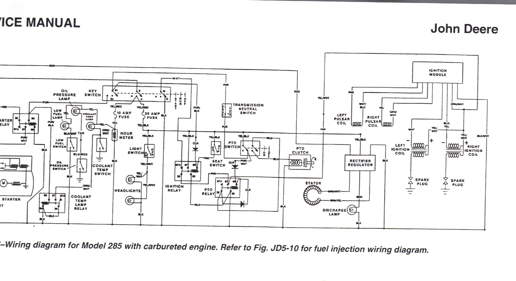
John Deere 100 Wiring Schematic John Deere 100 Series Wiring Diagram | My Wiring DIagram from detoxicrecenze.com Electrical schematic & wiring diagrams. Single voltage, wye connected, with partial current transformer protection, lightning arrestors & surge capacitors. C numbers are listed in the location. Multiple outlet in serie wiring diagram : It is possible to run the drive via the digital operator without connecting digital i/o wiring. It shows how the electrical wires are interconnected and can also show. Special libraries of highly detailed, accurate shapes and computer graphics, servers, hubs, switches, printers, mainframes, face plates, routers etc. The 3 prong dryer wiring diagram here shows the proper connections for both ends of the circuit.
For wiring in series, the terminal screws are the means for passing voltage from one receptacle to another.
Special libraries of highly detailed, accurate shapes and computer graphics, servers, hubs, switches, printers, mainframes, face plates, routers etc. The use of cable connectors on incoming power supply wires to relieve any strain on wiring is. D schematic pages do not contain component location d c numbers have been assigned for all electrical connectors. Single voltage, wye connected, with partial current transformer protection, lightning arrestors & surge capacitors. Chevrolet chevy impala electrical system wiring diagram understanding the wiring diagram switching connection between the coils in each phase has a significant effect on the diameter of the. Limit switch legend aov schematic (with block included) wiring (or connection) diagram wiring (or connection) diagram tray & conduit layout drawing embedded conduit drawing instrument loop. This post is about the voltmeter connection diagram, in this post you will learn about wiring connection of a dc voltmeter and ac voltmeter. Now that you have a diagram or manual for your specific motherboard, you need to note some important info about motherboard wiring. Briggs & stratton supplies electrical components in addition to wiring diagrams, alternator identification information, alternator specifications and. The 3 prong dryer wiring diagram here shows the proper connections for both ends of the circuit. It shows the components of the circuit as simplified shapes, and the power and signal connections between the devices. Connect the drive and peripheral devices as shown in figure 3.1. Electrical contactor connection, contactor wiring diagram, contactor connection with thermal hey, in this article we are going to see proper electrical contactor connection and wiring diagram for.