Home
› Xor Gate Logic Diagram - Design Xor Gate Using Structural Modeling Vhdl Language In Xilinx All Basic Gates And Not Or Youtube : Popular interview question on internet.
Xor Gate Logic Diagram - Design Xor Gate Using Structural Modeling Vhdl Language In Xilinx All Basic Gates And Not Or Youtube : Popular interview question on internet.
Xor Gate Logic Diagram - Design Xor Gate Using Structural Modeling Vhdl Language In Xilinx All Basic Gates And Not Or Youtube : Popular interview question on internet.. Hence there is no voltage drop developed across the the seven logic gates are and, or, not, nand, nor, xor and x nor. You can find circuits using 4, 6, 8, 9, 10 or 12 transistors, again with varied strengths for the inputs and the output. The logic normally performed is boolean logic and is most commonly found in digital circuits. Where, 0 means off or false and 1 means on or true. Logic circuit diagram of nor gate.
My question is more like: Logic gates are primarily implemented electronically using diodes or transsitors. Detecting the phase relationship between signals. From the diagram, the nor gate is 1 only if both inputs are 0. Coverting the equation to logic gates makes the following diagram.
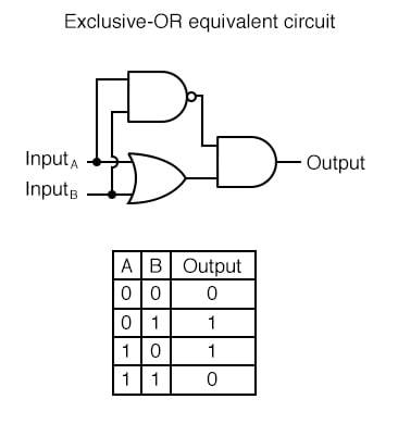
Exclusive Or Gate Xor Gate from www.electronicshub.org Detecting the phase relationship between signals. Logic circuit diagram of nor gate. When you observe the truth table of xor, you can find that if any input is high, the result is high or true. A logic gate performs a logical operation on one or more logic inputs and produces a single logic output. From the diagram, the nor gate is 1 only if both inputs are 0. Xor gate, now i need to construct this gate using only 4 nand gate. Xor gate or exclusive or tutorial. The logic normally performed is boolean logic and is most commonly found in digital circuits.
If both inputs are different then the output will be 'true'.
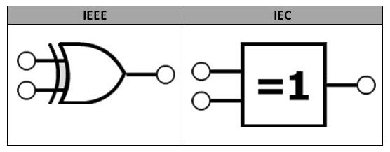
Notice how each gate connects the variables together just like the logic blocks in the code above. Xor gate (sometimes eor, or exor and pronounced as exclusive or) is a digital logic gate that gives a true (1 or high) output when the number of true inputs is odd. A phase detector or phase comparator is a logic circuit that generates an analog output voltage signal which represents the difference in phase between two logic signal inputs. Challenge 1 logic gates using xor and and gates to add 2 binary digits translate the the following logical expression into both a truth table and a logic diagram. Imagine the first person in history figure out this formula, how can he. A logic gate performs a logical operation on one or more logic inputs and produces a single logic output. From the diagram, the nor gate is 1 only if both inputs are 0. It can also be done using nor logic gates in the same way. An xor gate (sometimes referred to by its extended name, exclusive or gate) is a digital logic gate with two or more inputs and one output that performs exclusive disjunction. Popular interview question on internet. (click logic gates diagram creatorcreate your own logic gates diagram. If an xor gate has more than two inputs, then its behavior depends on its implementation. This is a diagram of a not gate.
It can also be done using nor logic gates in the same way. Learning objectives in this post you will practise drawing logic gates diagrams using the following logic gates: Where, 0 means off or false and 1 means on or true. After the overview of all the basic logic gates. The second last logic gate in this verilog course is the xor logic gate.
Exclusive Or Gate from hyperphysics.phy-astr.gsu.edu Logic gates are very important and they serve as the building blocks to digital logic circuits using combinational logic. The cmos xor gate circuit diagram is as shown in figure 3. When you observe the truth table of xor, you can find that if any input is high, the result is high or true. Xor gate or exclusive or tutorial. The implementation of these logic gates is explained with the aid of an examples which we recommend you solve along with the video. Detecting the phase relationship between signals. Logic circuit diagram of nor gate. Each animated diagram shows the input and output conditions for one of the seven logic functions in its two input form.
Drive xor gate from nand gateusing digital logic.
Learning objectives in this post you will practise drawing logic gates diagrams using the following logic gates: If both inputs are different then the output will be 'true'. Let's code the gate using the three modeling types: Popular interview question on internet. Gate inputs are driven by voltages having two nominal values, e.g. Logic xor gate diagram : This is a diagram of a not gate. The second last logic gate in this verilog course is the xor logic gate. The implementation of these logic gates is explained with the aid of an examples which we recommend you solve along with the video. Xor gates have two bits of input and a single bit of output. Notice how each gate connects the variables together just like the logic blocks in the code above. Xor gate, now i need to construct this gate using only 4 nand gate. If an xor gate has more than two inputs, then its behavior depends on its implementation.
However, if we take the other two unused conditions from the truth table that make the xor operation false. When both the inputs applied are of 0 volts both the transistors q1 and q2 are off. Xor gates have two bits of input and a single bit of output. 0v and 5v representing logic 0 and logic 1 respectively. (click logic gates diagram creatorcreate your own logic gates diagram.
Multiple Input Gates Logic Gates Electronics Textbook from www.allaboutcircuits.com Imagine the first person in history figure out this formula, how can he. An xor gate (sometimes referred to by its extended name, exclusive or gate) is a digital logic gate with two or more inputs and one output that performs exclusive disjunction. If both inputs are different then the output will be 'true'. The output of the xor gate is low for similar inputs while for the dissimilar inputs the output is high. Logic xor gate diagram : After the overview of all the basic logic gates. Xor gates have two bits of input and a single bit of output. • as with gates, we can describe the operations of entire circuits using three notations.
Xor gate, now i need to construct this gate using only 4 nand gate.
The diagrams below show two ways that the nand logic gate can be configured to produce a not gate. Xor gate as phase detector: Notice how each gate connects the variables together just like the logic blocks in the code above. My question is more like: The cmos xor gate circuit diagram is as shown in figure 3. It is an electronic circuit having not gate is also known as inverter. After the overview of all the basic logic gates. And gate or gate xor gate not gate use our logic gates diagram tool to create the diagrams as follow: Understanding shear force and bending moment diagrams. When you observe the truth table of xor, you can find that if any input is high, the result is high or true. Xor gates have two bits of input and a single bit of output. It has one input a and one output y. Logic gates are very important and they serve as the building blocks to digital logic circuits using combinational logic.