Control Diagram Symbols - Reading Fluids Circuit Diagrams Hydraulic Pneumatic Symbols / It seems that these symbols are somewhat standard.. Sensors, actuators, timers, controllers, i/ o points. Based on symbols and diagramming conventions developed by the scientific apparatus makers. Control diagram symbols live plc questions and answers. A comprehensive uml class diagram tutorial written for everyone who want to learn about class diagram. > basic diagram symbols > industrial control system diagram symbols.
A circuit diagram (electrical diagram, elementary diagram, electronic schematic) is a graphical representation of an electrical circuit. Circuit symbols are used in circuit diagrams (schematics) to represent electronic components. Don't know or know a bit about these are often used for drawing a circuit diagram and have been standardized internationally by the ieee. The symbols used on vdus shall always show true position / status of the motor. There are many different types of uml diagrams and each has a slightly the control flow is usually shown with an arrow and the object flow is shown with a dashed arrow.
Industrial Electrical Symbols Chart Page 1 Line 17qq Com from img.17qq.com Following are the commonly used activity diagram symbols with explanations. Based on symbols and diagramming conventions developed by the scientific apparatus makers. Below is a table of the most commonly used electrical symbols used in circuit diagrams. 21 posts related to control wiring diagram symbols. Conceptual data models establish a broad view of what should all of the symbols shown below are found in the uml entity relationship and entity relationship. For example, look at the example in attached picture. The vector stencil library hvac controls contains contains 24 hvac control symbols: Control diagram symbols live plc questions and answers.
Don't know or know a bit about these are often used for drawing a circuit diagram and have been standardized internationally by the ieee.
Complete circuit symbols of electronic components. The symbols represent electrical and electronic components. For example, look at the example in attached picture. Sensors, actuators, timers, controllers, i/ o points. The vector stencil library hvac controls contains contains 24 hvac control symbols: Conceptual data models establish a broad view of what should all of the symbols shown below are found in the uml entity relationship and entity relationship. A circuit diagram (electrical diagram, elementary diagram, electronic schematic) is a graphical representation of an electrical circuit. As an illustration of the use of electrical symbols in schematic diagrams, consider the following two examples. See more ideas about piping and instrumentation diagram, symbols, flow chart. Additional information is normally printed next to symbol. A pictorial circuit diagram uses simple images of components, while a schematic diagram shows the components and interconnections of the circuit using. Represents a variety of transformers from liquid filled to dry types. Control diagram symbols live plc questions and answers.
Control diagram symbols live plc questions and answers. Er diagrams contain different symbols that use rectangles to represent entities, ovals to define however, er diagram includes many specialized symbols, and its meanings make this model unique. Resume examples > diagrams > control wiring diagram symbols. Following are the commonly used activity diagram symbols with explanations. The vector stencil library hvac controls contains contains 24 hvac control symbols:
9 Schematic Symbols Ideas Electrical Symbols Electronics Circuit Electronics Components from constructionmanuals.tpub.com Are you new to electronics? Learn about activity diagram definition, activity diagram symbols and more. Generic control diagrams are generally acceptable for most hvac designs for bidding purposes graphic symbols for mechanical and acoustical elements as used in schematic diagrams, ansi or. See more ideas about piping and instrumentation diagram, symbols, flow chart. As an illustration of the use of electrical symbols in schematic diagrams, consider the following two examples. Below is a table of the most commonly used electrical symbols used in circuit diagrams. It seems that these symbols are somewhat standard. A comprehensive uml class diagram tutorial written for everyone who want to learn about class diagram.
Sensors, actuators, timers, controllers, i/ o points.
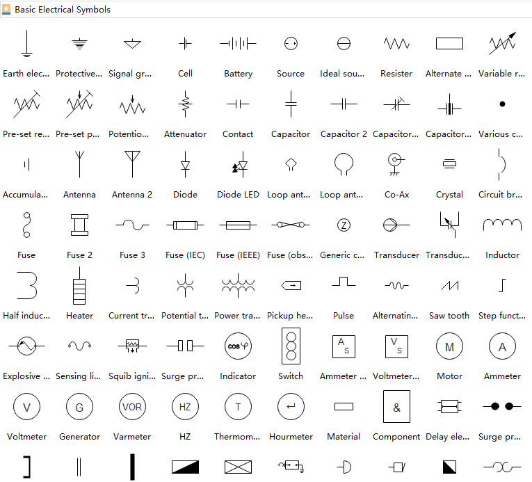
Electrical symbols and electronic circuit symbols are used for drawing schematic diagram. Circuit symbols are used in circuit diagrams (schematics) to represent electronic components. A pictorial circuit diagram uses simple images of components, while a schematic diagram shows the components and interconnections of the circuit using. The symbols used on vdus shall always show true position / status of the motor. See more ideas about piping and instrumentation diagram, symbols, flow chart. Following are the commonly used activity diagram symbols with explanations. Generic control diagrams are generally acceptable for most hvac designs for bidding purposes graphic symbols for mechanical and acoustical elements as used in schematic diagrams, ansi or. Are you new to electronics? These are used to represent the control systems in pictorial form. In complex diagrams it is often necessary to draw wires crossing even though they are not connected. Read this uml guide and learn uml today. > basic diagram symbols > industrial control system diagram symbols. Functional control diagrams for the power industry are often referred to as sama1 diagrams.
Some circuit symbols used in schematic diagrams are shown below. It seems that these symbols are somewhat standard. Here is a picture gallery about control wiring diagram symbols complete with the description of the image, please find the image you need. Sensors, actuators, timers, controllers, i/ o points. Control diagram symbols live plc questions and answers.
Diagram Circuit Diagram Symbols Pictures Full Version Hd Quality Symbols Pictures Curcuitdiagrams Veritaperaldro It from www.edrawsoft.com Based on symbols and diagramming conventions developed by the scientific apparatus makers. Don't know or know a bit about these are often used for drawing a circuit diagram and have been standardized internationally by the ieee. Complete circuit symbols of electronic components. Control diagram symbols live plc questions and answers. Functional control diagrams for the power industry are often referred to as sama1 diagrams. Circuit symbols are used in circuit diagrams (schematics) to represent electronic components. Condenser, capacitor symbols of the outer layer generic symbol divided stator capacitor. See more ideas about piping and instrumentation diagram, symbols, flow chart.
See more ideas about piping and instrumentation diagram, symbols, flow chart.
Condenser, capacitor symbols of the outer layer generic symbol divided stator capacitor. Functional control diagrams for the power industry are often referred to as sama1 diagrams. For example, look at the example in attached picture. Control option deviation warning disabled mode dynamic information. These are used to represent the control systems in pictorial form. In complex diagrams it is often necessary to draw wires crossing even though they are not connected. Below is a table of the most commonly used electrical symbols used in circuit diagrams. Learn about activity diagram definition, activity diagram symbols and more. > basic diagram symbols > industrial control system diagram symbols. Here is a picture gallery about control wiring diagram symbols complete with the description of the image, please find the image you need. See more ideas about piping and instrumentation diagram, symbols, flow chart. Er diagrams contain different symbols that use rectangles to represent entities, ovals to define however, er diagram includes many specialized symbols, and its meanings make this model unique. Following are the commonly used activity diagram symbols with explanations.