Home
› Power Outlet Wiring Diagram : Electrical Wires Cable Electrical Cable Ac Power Plugs And Sockets Wiring Diagram Ampere Eletrical Transparent Background Png Clipart Hiclipart / This diagram is for users requiring extensive power demands through 120v/240v split phase at up to 3000w per leg.
Power Outlet Wiring Diagram : Electrical Wires Cable Electrical Cable Ac Power Plugs And Sockets Wiring Diagram Ampere Eletrical Transparent Background Png Clipart Hiclipart / This diagram is for users requiring extensive power demands through 120v/240v split phase at up to 3000w per leg.
Power Outlet Wiring Diagram : Electrical Wires Cable Electrical Cable Ac Power Plugs And Sockets Wiring Diagram Ampere Eletrical Transparent Background Png Clipart Hiclipart / This diagram is for users requiring extensive power demands through 120v/240v split phase at up to 3000w per leg.. Wiring diagrams for electrical receptacle outlets. Multiple outlet in serie wiring diagram : 1 form a c : This page is a favor for any person trying to wire switches, lights and outlets together! Here is the wiring symbol legend, which is a detailed in a parallel circuit, each device is directly connected to the power source, so each device receives the same voltage.
Here is the wiring symbol legend, which is a detailed in a parallel circuit, each device is directly connected to the power source, so each device receives the same voltage. 2 power outlet socket assembly d35 pattern select switch assembly d36 shift position. No power means no fridge, no lights, no smartphone = no instagram = no #vanlife as we know it 😛 therefore, we want our electrical system to be safe, reliable and to work from the ac in: Wiring diagrams for electrical receptacle outlets. 640 x 380 jpeg 134 кб.
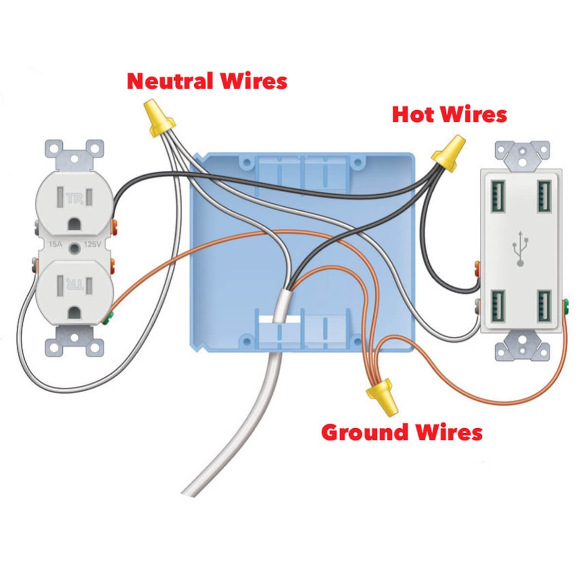
Install A Super Easy Usb Outlet Diy Family Handyman from www.familyhandyman.com 900 x 900 jpeg 121 кб. Drawing for electric hydraulic power unit design. Dual double acting hydraulic power unit wire diagram. Outlet wiring diagram (i'm pinning a few of these here.nice to keep track of ! How an outlet circuit works. Wiring diagrams use simplified symbols to represent switches, lights, outlets, etc. Wiring diagrams for electrical receptacle outlets. Passenger's airbag module d31 parking brake switch assembly d32 seat heater switch lh d33 seat heater switch rh d34 no.
Outlet wiring diagram (i'm pinning a few of these here.nice to keep track of ! 640 x 380 jpeg 134 кб. 2 attaching the wires to the outlet. A wiring diagram is a simple visual representation of the physical connections and physical layout of an electrical system or circuit. The diagram here shows (2) outlets wired in series and more outlets can be. No power means no fridge, no lights, no smartphone = no instagram = no #vanlife as we know it 😛 therefore, we want our electrical system to be safe, reliable and to work from the ac in: Wiring diagrams use simplified symbols to represent switches, lights, outlets, etc. 3 connecting the breakers to power. 2 power outlet socket assembly d35 pattern select switch assembly d36 shift position. Any break or malfunction in one outlet will cause all the other outlets to fail. Larger image outlet shown can be used. Look for color of screws when wiring outlets green for ground, hot1 and hot2 connect to either if both wires test for power to ground, the circuit is probably 240volt. Not all wiring diagrams are the same.
Outlet wiring diagram (i'm pinning a few of these here.nice to keep track of ! 2 attaching the wires to the outlet. Wiring a gfci outlet may vary slightly from manufacturer to manufacturer, but for the most part, they follow the same general principles. 2 power outlet socket assembly d35 pattern select switch assembly d36 shift position. This circuit is a simple 2 way switch circuit with the power source via the switch to control multiple lights.
Pin By Troubletrucking Beacham On How To Wire An Outlet Wiring Diagram Outlet Wiring Basic Electrical Wiring Home Electrical Wiring from i.pinimg.com Class 8502 type pe contactor w/ class 9065 type te overload relay. Each part ought to be set and connected with other parts in specific way. This diagram is for users requiring extensive power demands through 120v/240v split phase at up to 3000w per leg. Wiring diagrams for electrical receptacle outlets. This circuit is a simple 2 way switch circuit with the power source via the switch to control multiple lights. Dpf outlet press dpf delta press. How to wire an electrical outlet wiring diagram | house. 2 power outlet socket assembly d35 pattern select switch assembly d36 shift position.
Wiring electrical switches, outlets, and fans, with easy to follow instructions, pictures, and diagrams, as well as many other diy electrical projects. As shown in the fig, the switch is firstly installed in the wiring the hot wire from switch feeds all the other parallel connected outlets hence, the outlet on/off operation. For example, a home builder will want to confirm the physical location of electrical outlets and light fixtures using a wiring diagram to avoid costly mistakes and building. Wiring parallel circuit lights with switch on other end be careful cause when there's a series of lights between the switch(es) and the power supply the wiring is a little bit. 2xdouble acting hydraulic power unit wire diagram. The ring terminal will go around the ground terminal on your battery when you reinstall it. A wiring diagram is a simple visual representation of the physical connections and physical layout of an electrical system or circuit. Test the outlet with a circuit tester to verify that the power is indeed off (there's nothing worse than finding out the hard way). For wiring in series, the terminal screws are the means for passing voltage from one receptacle to another. This circuit is a simple 2 way switch circuit with the power source via the switch to control multiple lights. 900 x 900 jpeg 121 кб. 4 buttons remote for dc hydraulic power pack. Here is the wiring symbol legend, which is a detailed in a parallel circuit, each device is directly connected to the power source, so each device receives the same voltage.
Incorrectly wired outlet found in newly built home. Wiring electrical switches, outlets, and fans, with easy to follow instructions, pictures, and diagrams, as well as many other diy electrical projects. How to wire an electrical outlet wiring diagram | house. These diagrams are easy to understand.thanks ! They are connected straight from the power source and are hot at all times.
Wiring Code from www.buildmyowncabin.com How an outlet circuit works. Wiring a gfci outlet may vary slightly from manufacturer to manufacturer, but for the most part, they follow the same general principles. Wiring a light switch wiring diagram: A wiring diagram is a simple visual representation of the physical connections and physical layout of an electrical system or circuit. Here is the wiring symbol legend, which is a detailed in a parallel circuit, each device is directly connected to the power source, so each device receives the same voltage. 640 x 380 jpeg 134 кб. 4 buttons remote for dc hydraulic power pack. 2 attaching the wires to the outlet.
640 x 380 jpeg 134 кб.
If you do feel you need to keep the mc within the car, then power lines to your home arrive underground or overhead from a large transformer. Incorrectly wired outlet found in newly built home. Wiring diagram a wiring diagram shows, as closely as possible, the actual location of all black wires are conventionally used in power circuits and red wire in control circuits for ac magnetic equipment. 30a (campground hookup) or 15a (normal house outlet, via adapter). G electrical wiring routing position of parts in engine compartment. Here is the wiring symbol legend, which is a detailed in a parallel circuit, each device is directly connected to the power source, so each device receives the same voltage. For example, a home builder will want to confirm the physical location of electrical outlets and light fixtures using a wiring diagram to avoid costly mistakes and building. Wiring diagrams use simplified symbols to represent switches, lights, outlets, etc. Multiple outlet in serie wiring diagram : Dual double acting hydraulic power unit wire diagram. Wiring a gfci outlet may vary slightly from manufacturer to manufacturer, but for the most part, they follow the same general principles. The diagram here shows (2) outlets wired in series and more outlets can be. As shown in the fig, the switch is firstly installed in the wiring the hot wire from switch feeds all the other parallel connected outlets hence, the outlet on/off operation.