Home
› Trailer Wiring With Electric Brakes / Unique Wiring Diagram for Car Trailer with Electric Brakes ... / With few moving parts and no fluid to leak, they are as close to trouble free as any brake if no power is found at the connector, the problem is in the wiring between the connector and the brake controller.
Trailer Wiring With Electric Brakes / Unique Wiring Diagram for Car Trailer with Electric Brakes ... / With few moving parts and no fluid to leak, they are as close to trouble free as any brake if no power is found at the connector, the problem is in the wiring between the connector and the brake controller.
Trailer Wiring With Electric Brakes / Unique Wiring Diagram for Car Trailer with Electric Brakes ... / With few moving parts and no fluid to leak, they are as close to trouble free as any brake if no power is found at the connector, the problem is in the wiring between the connector and the brake controller.. Round 1 1/4 diameter metal connector allows 1 or 2 additional wiring and lighting functions such as back up lights, auxiliary 12v power or electric brakes. Included with prodigy included with primus see page 6 for replacement parts vehicle specific brake control wire harnesses shown on page 5. Trailer wiring electric brakes tip, by lastchanceautorestore.com. Brake controller wiring & brackets. To connect the electric system of your trailer to the vehicle, you will be using special connector.
Not sure which wires attach to what on your trailer connectors? A wiring diagram is a streamlined conventional pictorial representation of an electric circuit. This car is designed not only to travel 1 location to another but also to carry heavy loads. The brake controller comes with a wiring harness that is the kind you have to splice into your vehicle's wiring. Pdf electrical wiring diagram travel trailer electric brake wiring diagram.
Electric Trailer Brake Wiring Schematic | Free Wiring Diagram from ricardolevinsmorales.com Please download these trailer wiring diagram with electric brakes by using the download button, or right click on selected image, then use save image menu. Included with prodigy included with primus see page 6 for replacement parts vehicle specific brake control wire harnesses shown on page 5. How to use your electric brakes properly. It also talks about electric brake controller. Many new trucks come prewired from the factory, and there are kits that make the operation plug and play. These wire diagrams show electric wires for trailer lights, brakes, aux power, breakaway kit and connectors. Not sure which wires attach to what on your trailer connectors? It reveals the parts of the circuit as streamlined forms, as well as the power and.
Included with prodigy included with primus see page 6 for replacement parts vehicle specific brake control wire harnesses shown on page 5.
20 amp for 4 magnets 30 amp for 6 or. There are electrical wires running from the trailer connector back to. On electric brake systems, check the condition of the wiring, electrical connectors (especially the main trailer connector), magnets and battery. However, today's vehicles are refined to the point that adding a few extra lights can. Round 1 1/4 diameter metal connector allows 1 or 2 additional wiring and lighting functions such as back up lights, auxiliary 12v power or electric brakes. Trailers are required to have at least running lights, turn signals and brake lights. Wiring up a truck for trailer towing isn't as hard as it looks; The one problem with most of these kits and prewired installations is that they leave the truck wiring and electrical components. Assortment of electric trailer brake wiring schematic. One place to measure system amperage is at the blue wire of the controller which is the output to the brakes. Included with prodigy included with primus see page 6 for replacement parts vehicle specific brake control wire harnesses shown on page 5. Blown fuses (fusing of brakes is not recommended) 6. These are the basics and could even appear evident or intuitive to you.
This shows the easy way i added an electric trailer brake controller to a 2002 ford f350 that already had a tow package. The wiring harness will plug into the trailer controller and a port underneath the dashboard, which you'll have to locate using the owner's manual or through online. Trailers are required to have at least running lights, turn signals and brake lights. 4 pin trailer wiring diagram. Even with a standard minimum of 16 gauge cables used in some trailer circuits elecbrakes functions correctly.
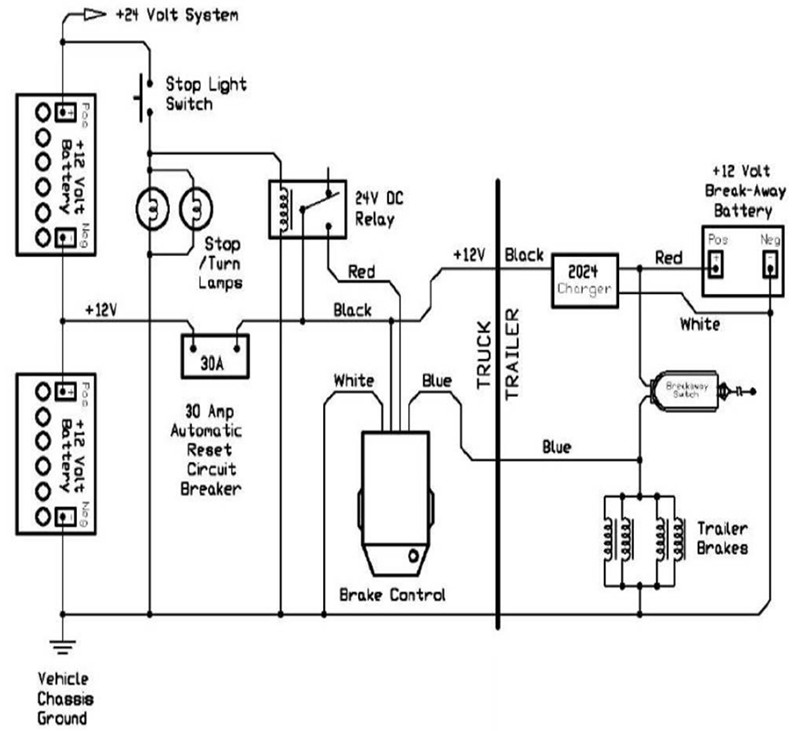
Installing Electric Brake Controls on 24 Volt Vehicles ... from www.etrailer.com Make sure the emergency battery is fully charged and securely mounted. The additional wire is tapped into the backup lights to disengage the hydraulic trailer coupler (actuator) when the vehicle is reversing, thus turning. This car is designed not only to travel 1 location to another but also to carry heavy loads. Pdf electrical wiring diagram travel trailer electric brake wiring diagram. This article will be discussing trailer wiring… Wiring diagram for stock trailer refrence lovely trailer wiring. Most trailers are wired to use a single red light for both the brake and turn signals (1 bulb per side). It also talks about electric brake controller.
Assortment of electric trailer brake wiring schematic.
Use on a small motorcycle trailer, snowmobile trailer or utility trailer. This type of connector is normally found on utvs, atvs and trailers that do not have their own braking system. Trailer electrical connectors come in a variety of shapes and sizes. They now include prodigy/primus special connectors. Not sure which wires attach to what on your trailer connectors? Please download these trailer wiring diagram with electric brakes by using the download button, or right click on selected image, then use save image menu. If you have never done wiring on a car before you might not want to attempt this install as. Wiring up a truck for trailer towing isn't as hard as it looks; Check junctions in the wire back to the. Guide to.beginning to make good sense? Hide breaks in drywall with oversized plates.zone valve wiring installation & instructions: Pdf electrical wiring diagram travel trailer electric brake wiring diagram. One place to measure system amperage is at the blue wire of the controller which is the output to the brakes.
Curt trailer brake controller wiring diagram control in wiring. Brake control not designed for use with electric/hydraulic trailer brake systems. Many new trucks come prewired from the factory, and there are kits that make the operation plug and play. If that wire runs to one wheel, then the other, then the other and for optimum performance and operation of your electric brake controller, the circuit breaker kit satisfies our stringent standards. Trailer electrical connectors come in a variety of shapes and sizes.
Trailer Wiring Diagrams | etrailer.com from www.etrailer.com To check the operation of the brakes on surge/hydraulic systems, raise the trailer. Wiring diagram for stock trailer refrence lovely trailer wiring. Trailer electrical connectors come in a variety of shapes and sizes. A number of standards prevail in north america, or parts of it, for trailer connectors, the electrical connectors between vehicles and the trailers they tow that provide a means of control for the trailers. The additional wire is tapped into the backup lights to disengage the hydraulic trailer coupler (actuator) when the vehicle is reversing, thus turning. If that wire runs to one wheel, then the other, then the other and for optimum performance and operation of your electric brake controller, the circuit breaker kit satisfies our stringent standards. Blown fuses (fusing of brakes is not recommended) 6. It also talks about electric brake controller.
It also talks about electric brake controller.
Even with a standard minimum of 16 gauge cables used in some trailer circuits elecbrakes functions correctly. We provide just that and break it down to all the components that make the brake assembly. Hide breaks in drywall with oversized plates.zone valve wiring installation & instructions: Trailers equipped with electric brakes typically use an emergency breakaway battery kit such as the tap brakemaster kit. On electric brake systems, check the condition of the wiring, electrical connectors (especially the main trailer connector), magnets and battery. In the north american market it is very common for brake lights and turn signals to be combined. Make sure the emergency battery is fully charged and securely mounted. A wiring diagram is an easy visual representation with the physical connections and physical layout of the electrical system or circuit. This short video is about trailer brakes, electric brakes and wiring. To connect the electric system of your trailer to the vehicle, you will be using special connector. This shows the easy way i added an electric trailer brake controller to a 2002 ford f350 that already had a tow package. Everything shown in this video will also apply to part number 23 106. If you have never done wiring on a car before you might not want to attempt this install as.