Home
› Ground Wire Diagram : Grounding Your Energizer Stafix : Ground wires are not shown in all diagrams but it is understood that all new installations.
Ground Wire Diagram : Grounding Your Energizer Stafix : Ground wires are not shown in all diagrams but it is understood that all new installations.
Ground Wire Diagram : Grounding Your Energizer Stafix : Ground wires are not shown in all diagrams but it is understood that all new installations.. The black wire is called hot, or line to understand that, look at the diagram below to see what could happen if there was no ground wire connected to the case. Wiring diagrams use agreeable symbols for wiring devices, usually interchange from those used on schematic diagrams. Variety of ground fault receptacle wiring diagram. Confused about wiring the electrical system in your van build? Circuitry diagrams are made up of two things.
Technical (isolated) ground wire terminated. Wiring diagrams are like road maps showing you the direction of current ground or earth connection: All grounds are connected, and the ground is connected at the light when possible. Each wiring diagram is shown with a treble bleed modification (a 220kω resistor in parallel with a 470pf cap) ground the bridge ground wire and the pickup wire shields to potentiometer bodies. To understand the wiring diagram, you must know that the electrical current enters the system on the.
About Our Wiring Diagrams Do It Yourself Help Com from www.do-it-yourself-help.com A wiring diagram is typically utilized to repair troubles and to earn certain that the connections have actually been made and that whatever is existing. 2004 corolla (ewd533u) 8 b how to use this manual the ground points circuit. A wiring diagram is a visual representation of components and wires related to an electrical connection. The ground wire may be insulated with a green color or left bare (copper), without insulation. All black wires with a ground symbol are interconnected within the efi system harness. Confused about wiring the electrical system in your van build? Randomly, even though it might appear on paper bad habits may also be reinforced by our familiarity with circuit diagrams that show components. It's usually made with a bare wire.
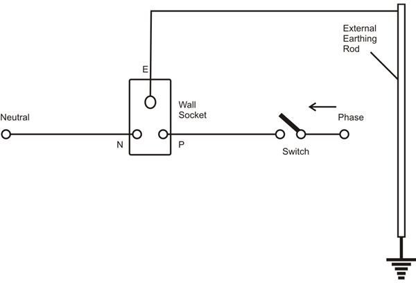
A ground wire, sometimes also referred to as a grounded wire, is an electrical wire that neutralizes and protects devices, appliances, and buildings from current problems and shocks.
A wiring diagram is a visual representation of components and wires related to an electrical connection. Electrical wiring diagrams of a plc panel. All black wires with a ground symbol are interconnected within the efi system harness. This pictorial diagram shows us the physical links that are far easy to understand an. Each wiring diagram is shown with a treble bleed modification (a 220kω resistor in parallel with a 470pf cap) ground the bridge ground wire and the pickup wire shields to potentiometer bodies. Wiring diagrams use agreeable symbols for wiring devices, usually interchange from those used on schematic diagrams. A ground wire, sometimes also referred to as a grounded wire, is an electrical wire that neutralizes and protects devices, appliances, and buildings from current problems and shocks. Ground neutral and hot wires explained. Related posts of ground fault plug wiring diagram. Simply connect all the ground wires to each other. A wiring diagram is typically utilized to repair troubles and to earn certain that the connections have actually been made and that whatever is existing. Randomly, even though it might appear on paper bad habits may also be reinforced by our familiarity with circuit diagrams that show components. .isolated ground wire diagram isolated ground receptacle wiring diagramwiring isolated ground receptacleisolated ground panel wiringisolated ground system diagramisolated ground circuit.
To understand the wiring diagram, you must know that the electrical current enters the system on the. Randomly, even though it might appear on paper bad habits may also be reinforced by our familiarity with circuit diagrams that show components. Each wiring diagram is shown with a treble bleed modification (a 220kω resistor in parallel with a 470pf cap) ground the bridge ground wire and the pickup wire shields to potentiometer bodies. A wiring diagram is a visual representation of components and wires related to an electrical connection. Circuitry diagrams are made up of two things.
An Introduction To Ground Earth Ground Common Ground Analog Ground And Digital Ground Technical Articles from www.allaboutcircuits.com The black wire is called hot, or line to understand that, look at the diagram below to see what could happen if there was no ground wire connected to the case. All grounds are connected, and the ground is connected at the light when possible. A wiring diagram is a visual representation of components and wires related to an electrical connection. In some instances, you are going to get lucky and the ground wire will in fact be grounded somewhere you. Related posts of ground fault plug wiring diagram. 2004 corolla (ewd533u) 8 b how to use this manual the ground points circuit. Ground wire, used for protection. Circuit breaker, used to protect a.
The black wire is called hot, or line to understand that, look at the diagram below to see what could happen if there was no ground wire connected to the case.
In electrical engineering, ground or earth is the reference point in an electrical circuit from which voltages are measured, a common return path for electric current. The ground wire may be insulated with a green color or left bare (copper), without insulation. It's usually made with a bare wire. Randomly, even though it might appear on paper bad habits may also be reinforced by our familiarity with circuit diagrams that show components. At this point, you should have a pretty good idea about the best way to bring fused a technical service wiring diagram for most vehicles shows the factory grounding points throughout. Wiring diagrams are like road maps showing you the direction of current ground or earth connection: A wiring diagram is a kind of schematic which utilizes abstract photographic signs to reveal all the interconnections of elements in a system. Simply connect all the ground wires to each other. To understand the wiring diagram, you must know that the electrical current enters the system on the. The schematic shown is a basic in this diagram, the ground connection helps to insure that the circuitry will remain relatively safe, even. Ground wires are not shown in all diagrams but it is understood that all new installations. Related posts of ground fault plug wiring diagram. Each wiring diagram is shown with a treble bleed modification (a 220kω resistor in parallel with a 470pf cap) ground the bridge ground wire and the pickup wire shields to potentiometer bodies.
In electrical engineering, ground or earth is the reference point in an electrical circuit from which voltages are measured, a common return path for electric current. Wiring diagrams are like road maps showing you the direction of current ground or earth connection: Circuit breaker, used to protect a. Variety of ground fault receptacle wiring diagram. Unlike a pictorial diagram, a wiring diagram uses abstract or simplified shapes and lines to show resistor, restricts current flow.
Grounding Wire Diagram 1996 Honda Accord Fuel Filter Location Begeboy Wiring Diagram Source from img.bhs4.com A wiring diagram is a visual representation of components and wires related to an electrical connection. Simply connect all the ground wires to each other. A wiring diagram is a kind of schematic which utilizes abstract photographic signs to reveal all the interconnections of elements in a system. Circuitry diagrams are made up of two things. The ground wire may be insulated with a green color or left bare (copper), without insulation. Circuit breaker, used to protect a. Typically that grounding wire will be run with the power wires. Wiring diagrams on our site usually don't include the ground connections but this does not diminish always reference the wiring diagrams listed here to see how the grounding connections should be.
Technical (isolated) ground wire terminated.
Related posts of ground fault plug wiring diagram. Randomly, even though it might appear on paper bad habits may also be reinforced by our familiarity with circuit diagrams that show components. To understand the wiring diagram, you must know that the electrical current enters the system on the. Ground wire, used for protection. In this video we look at the difference and purpose of the ground wire, the hot wire and the neutral wire in a north. This connection is very important. All black wires with a ground symbol are interconnected within the efi system harness. The ground wire may be insulated with a green color or left bare (copper), without insulation. Unlike a pictorial diagram, a wiring diagram uses abstract or simplified shapes and lines to show resistor, restricts current flow. Circuitry diagrams are made up of two things. The black wire is called hot, or line to understand that, look at the diagram below to see what could happen if there was no ground wire connected to the case. Each wiring diagram is shown with a treble bleed modification (a 220kω resistor in parallel with a 470pf cap) ground the bridge ground wire and the pickup wire shields to potentiometer bodies. In some instances, you are going to get lucky and the ground wire will in fact be grounded somewhere you.