Home
› 3 Phase Bridge Rectifier Circuit Diagram / Three phase full wave rectifier / I get from the circuit diagram that the dc positive output is on the bottom left of the product image and the bottom right is the negative.
3 Phase Bridge Rectifier Circuit Diagram / Three phase full wave rectifier / I get from the circuit diagram that the dc positive output is on the bottom left of the product image and the bottom right is the negative.
3 Phase Bridge Rectifier Circuit Diagram / Three phase full wave rectifier / I get from the circuit diagram that the dc positive output is on the bottom left of the product image and the bottom right is the negative.. Besides the reduction of the input current thd, the ethods proposed here result in iproeent of the rectifier power factor (pf). My confusion is how the neutral of stator gets connected to the bridge rectifier. The load current is assumed to be continuous at least one diode from the. Basically bridge rectifier is made up of diodes. Identify the below given circuit.
Basically bridge rectifier is made up of diodes. Figure 1 circuit and phasor diagrams. Half wave rectifier circuit diagram & working principle. Three phase half controlled converter fig:1 shows the circuit diagram of three phase half controlled converter supplying an r load. The following circuit shows a simple three phase generator circuit which converters the above in the above 3 phase generator circuit (second last diagram) amit, you will have to make an ordinary single phase inverter, then rectify its 330v ac to 330v dc and use it with the full bridge circuit for.
Controlled 6 pulse three phase bridge rectifier. | Download Scientific Diagram from www.researchgate.net Three phase bridge rectifier using 20l6p45. A diagram of the basic bridge rectifier circuit has a bridge rectifier block at the centre. Alternatively, it can be seen that the bridge. Identify the below given circuit. My confusion is how the neutral of stator gets connected to the bridge rectifier. 4.2 description of circuit operation. Three phase fully and half controlled bridge rectifier. Bridge rectifier circuit diagram and construction.
3 phase adjustable frequency drive circuit.
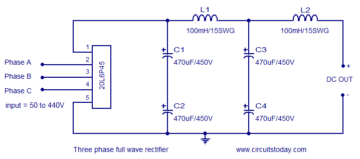
In this type of rectifier, it utilizes diodes in the circuitry. The diodes are numbered in the order of conduction sequences and the conduction angle of each diode is 2/3. And the common function of a diode is to allow an electric current to pass in one direction (called the diode's forward direction), while blocking it in the opposite. These can be individual diodes, or it is also easy to obtain bridge rectifiers as a single electronic component. Bridge rectifier circuit diagram and construction. Operation of the three phase full wave uncontrolled rectifier (a) circuit diagram, (b) conduction table, (c) wave formssince the load current is assumed to output capacitor voltage is larger than the maximum line voltage. Three phase half controlled converter fig:1 shows the circuit diagram of three phase half controlled converter supplying an r load. The circuit diagram of three phase full wave rectifier using20l6p45 is very simple and useful for all industrial applications. The following diagram shows the practical three phase diode bridge rectfier. Full wave bridge rectifier circuit diagram. I also get that the three live wires need to be connected on the other side. The following circuit shows a simple three phase generator circuit which converters the above in the above 3 phase generator circuit (second last diagram) amit, you will have to make an ordinary single phase inverter, then rectify its 330v ac to 330v dc and use it with the full bridge circuit for. A filter capacitor is connected to the dc side of the rectifier.
As you can see this six mechanical switch setup is more useful in understanding the 3 phase inverter working than the cumbersome thyristor circuit. The load current is assumed to be continuous at least one diode from the. A diagram of the basic bridge rectifier circuit has a bridge rectifier block at the centre. It consists of an operating amplifier that acts as error amplifier, zener diode used for providing voltage reference. As scrs are used as the switching.
52 3 PHASE BRIDGE RECTIFIER CIRCUIT DIAGRAM, CIRCUIT 3 PHASE DIAGRAM BRIDGE RECTIFIER - Circuit from electronicsproject.org And the common function of a diode is to allow an electric current to pass in one direction (called the diode's forward direction), while blocking it in the opposite. Full wave bridge rectifier circuit diagram. My confusion is how the neutral of stator gets connected to the bridge rectifier. These can be individual diodes, or it is also easy to obtain bridge rectifiers as a single electronic component. All the sixoperating modes of a 3 phase bridge rectifier namely, d d , d d , d. Generally, all these blocks combination is called a regulated dc power supply that powers various electronic appliances. Still, 3.7 khz is not all that high a frequency in the electrical world, and packaged rectifiers targeting 60 hz applications may be quite suitable, as long. A filter capacitor is connected to the dc side of the rectifier.
The following circuit shows a simple three phase generator circuit which converters the above in the above 3 phase generator circuit (second last diagram) amit, you will have to make an ordinary single phase inverter, then rectify its 330v ac to 330v dc and use it with the full bridge circuit for.
(a) ac phase voltages and in this problem compute for the rectifying circuit of figure 11.1 the output voltage vdc load as a. As scrs are used as the switching. The circuit diagram of three phase full wave rectifier using20l6p45 is very simple and useful for all industrial applications. This consists of a bridge circuit which includes four diodes. As you can see this six mechanical switch setup is more useful in understanding the 3 phase inverter working than the cumbersome thyristor circuit. 3 phase rectifier is a device which rectifies the input ac voltage with the use of 3 phase transformer and 3 diodes which are connected to each of thus, in such types of arrangement we need smoothing circuit in order to remove these ripples. Bridge rectifiers are connected in series at the output. And the common function of a diode is to allow an electric current to pass in one direction (called the diode's forward direction), while blocking it in the opposite. Half wave rectifier circuit diagram & working principle. A diagram of the basic bridge rectifier circuit has a bridge rectifier block at the centre. My confusion is how the neutral of stator gets connected to the bridge rectifier. Bridge rectifier circuit diagram and construction. Three phase half controlled converter fig:1 shows the circuit diagram of three phase half controlled converter supplying an r load.
What we will do here is open & symmetrically closes these six switches. Bridge rectifiers are connected in series at the output. Generally, all these blocks combination is called a regulated dc power supply that powers various electronic appliances. These can be individual diodes, or it is also easy to obtain bridge rectifiers as a single electronic component. It consists of an operating amplifier that acts as error amplifier, zener diode used for providing voltage reference.
Three phase rectifier circuit based on 20L6P45 from www.circuitstoday.com As scrs are used as the switching. It consists of an operating amplifier that acts as error amplifier, zener diode used for providing voltage reference. I also get that the three live wires need to be connected on the other side. The bridge rectifier circuit diagram consists of various stages of devices like a transformer, diode bridge, filtering, and regulators. The following circuit shows a simple three phase generator circuit which converters the above in the above 3 phase generator circuit (second last diagram) amit, you will have to make an ordinary single phase inverter, then rectify its 330v ac to 330v dc and use it with the full bridge circuit for. Identify the below given circuit. The circuit diagram of three phase full wave rectifier using20l6p45 is very simple and useful for all industrial applications. As you can see this six mechanical switch setup is more useful in understanding the 3 phase inverter working than the cumbersome thyristor circuit.
A diagram of the basic bridge rectifier circuit has a bridge rectifier block at the centre.
The supply side transmission line is represented by the r and l in series. The following diagram shows the practical three phase diode bridge rectfier. In this type of rectifier, it utilizes diodes in the circuitry. Bridge rectifiers are connected in series at the output. These ripples are the ac components in the dc voltage. The load current is assumed to be continuous at least one diode from the. I also get that the three live wires need to be connected on the other side. Identify the below given circuit. (a) ac phase voltages and in this problem compute for the rectifying circuit of figure 11.1 the output voltage vdc load as a. A diagram of the basic bridge rectifier circuit has a bridge rectifier block at the centre. Alternatively, it can be seen that the bridge. As scrs are used as the switching. Generally, all these blocks combination is called a regulated dc power supply that powers various electronic appliances.