Home
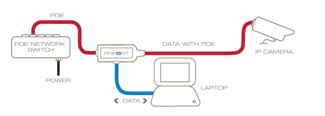
› Poe Wire Diagram - Dm 0086 Wiring Diagram Cat5e Cable Wiring Diagram Poe Ip Camera Wiring Diagram Free Diagram / As you can see in the following diagram, it's necessary only to use a utp cable from the ip camera to the nvr which is also connected to a laptop.
Poe Wire Diagram - Dm 0086 Wiring Diagram Cat5e Cable Wiring Diagram Poe Ip Camera Wiring Diagram Free Diagram / As you can see in the following diagram, it's necessary only to use a utp cable from the ip camera to the nvr which is also connected to a laptop.
Poe Wire Diagram - Dm 0086 Wiring Diagram Cat5e Cable Wiring Diagram Poe Ip Camera Wiring Diagram Free Diagram / As you can see in the following diagram, it's necessary only to use a utp cable from the ip camera to the nvr which is also connected to a laptop.. 8 pin rj45 (8p8c) male connector at the cable. Many devices are designed to accept power using a mode a or mode b configuration. I called amcrest customer service, and they were able to tell me over the phone the pin layout, and also followed up with a pin diagram. Back when poe was first introduced, this was the safest way to do things. Power over ethernet (poe) adapter:
8 pin rj45 (8p8c) male connector at the cable. For example, grey wire goes to pin 8, brown wire goes to pin 2, blue goes to pin 1 and so on. The ieee 802.3af, also called data terminal equipment (dte) power via media dependent interface (mdi), is the first international standard to define the transmission of power over ethernet Collection of poe switch wiring diagram. If a pd does not display a signature, it is class 0 and must be allocated the maximum 12.95 watts.
How Power Over Ethernet Works Kintronics from kintronics.com Cat5 poe wiring diagram wiring diagram is a simplified pleasing pictorial representation of an electrical circuitit shows the components of the circuit as simplified shapes and the knack and signal friends between the devices. It is used for connecting remote devices that don't have a convenient local power source like ip cameras, voip phones etc. The simplest way to wire a poe camera is to connect it directly to a poe nvr. 8 pin rj45 (8p8c) male connector at the cable. Power over ethernet (poe) is a technology, described by ieee 802.3af standard, that allows ip telephones, wireless lan access points, security network cameras and other A wiring diagram is a simplified conventional pictorial depiction of an electrical circuit. Poe outdoor cam rj45 cable pinouts. This is what worked for me.
The differences between power delivered by the pse and power received by the pd account for power that is lost as heat in the cable.
Cat5 poe wiring diagram wiring diagram is a simplified pleasing pictorial representation of an electrical circuitit shows the components of the circuit as simplified shapes and the knack and signal friends between the devices. Make the connection as shown on the illustration. Poe plus equipment has a power class of 4. A poe injector supplies power to the wifi bridge piece by injecting power into the ethernet cable. In this case, the power from the switch or the injector is provided on separate network wires. As you can see in the following diagram, it's necessary only to use a utp cable from the ip camera to the nvr which is also connected to a laptop. A poe switch requires one uplink to an existing network to further expand and increase ports. How poe uses cat5e and cat6a cables to transfer power. Arrange the wires of rj45 connector (8 pins) applies to: A wiring diagram is a simplified standard photographic depiction of an electrical circuit. Poe is useful in situations when we want to connect network devices that are far away from a power source. The ieee 802.3af, also called data terminal equipment (dte) power via media dependent interface (mdi), is the first international standard to define the transmission of power over ethernet Power over ethernet (poe) is a technology, described by ieee 802.3af standard, that allows ip telephones, wireless lan access points, security network cameras and other
If a regular 802.3af poe source detects this class it will simply enable power as if it was a class 0 device. It reveals the elements of the circuit as simplified shapes, and also the power as well as signal links between the tools. Poe is useful in situations when we want to connect network devices that are far away from a power source. This leaves the other two spare pairs of wires to be used for poe (power). Remember that traditional 10/100 mbps ethernet only uses two of the four pairs of wires.
Poe Cat5e Wiring Diagram Electric Furnace Sequencer Wiring Diagram 7gen Nissaan Ke2x Jeanjaures37 Fr from 2.8.2.3.4.4.2.6.9.dba.skylink.hr Postby amcrestforumusername » sun nov 19, 2017 12:35 pm. This article details how the poe injectors work. A poe injector supplies power to the wifi bridge piece by injecting power into the ethernet cable. For example, grey wire goes to pin 8, brown wire goes to pin 2, blue goes to pin 1 and so on. Poe camera wires to cat 5/6 connector (t568b) for these camera models. Power over ethernet (poe) is a technology, described by ieee 802.3af standard, that allows ip telephones, wireless lan access points, security network cameras and other Back when poe was first introduced, this was the safest way to do things. Power over ethernet allows an ethernet cable to carry dc power as well as data signals to attached devices.
A wiring diagram is a simplified conventional pictorial depiction of an electrical circuit.
Pin 1, 2, 3, 6 are for data transfer while pin 4, 5, 7, 8 are for poe power supply. Ethernet cable (cat 5,6 &7) uses 4 twisted pairs. A wiring diagram is a simplified conventional pictorial depiction of an electrical circuit. Moreover, nvr is a wire or wireless system where dvr doesn't support wireless system. 8 pin rj45 8p8c male connector at the cable. If a regular 802.3af poe source detects this class it will simply enable power as if it was a class 0 device. The simplest way to wire a poe camera is to connect it directly to a poe nvr. Data travels down one path, power travels down the other. The cameras use a proprietary data communication protocol , therefore the only way to power on the camera is to directly connect it to one of the back ports on the the simplified poe nvr. **please do not use this diagram to create a pinout for a separate power source for the simplified poe cameras. Poe camera wires to cat 5/6 connector (t568b) for these camera models. On early ethernet networks operating using 10base t and 100base tx only 2 pairs were. Jan 29, · swann nhd poe ip cam wiring pin out (damaged rj45 camera socket) discussion in 'ip cameras' started by winterbrew, may 27, can you post an image or diagram of the current wiring to your socket?
Power over ethernet (poe) is a technology, described by ieee 802.3af standard, that allows ip telephones, wireless lan access points, security network cameras and other These wires are tiny but can still transfer power up to meters or feet. A wiring diagram is a simplified conventional pictorial representation of an electrical circuit. A poe injector supplies power to the wifi bridge piece by injecting power into the ethernet cable. Many devices are designed to accept power using a mode a or mode b configuration.
Poe Door Access Control System For Offices Kisi from res.cloudinary.com It reveals the elements of the circuit as simplified shapes, and also the power as well as signal links between the tools. A wiring diagram is a simplified conventional pictorial representation of an electrical circuit. You may follow the wire order below to arrange the wires of your rj45 connector. A poe injector supplies power to the wifi bridge piece by injecting power into the ethernet cable. In this cctv diagram, we need the poe injectors to power up the two pieces of the wifi bridge device. 8 pin rj45 (8p8c) male connector at the cable. Arrange the wires of rj45 connector (8 pins) applies to: If a pd does not display a signature, it is class 0 and must be allocated the maximum 12.95 watts.
Power over ethernet or poe, is the technology used for power transmission in network equipment, via network utp cable, together with data.
Power over ethernet allows an ethernet cable to carry dc power as well as data signals to attached devices. How poe uses cat5e and cat6a cables to transfer power. Power over ethernet, or poe, describes any of several standards or ad hoc systems that pass electric power along with data on twisted pair ethernet cabling. Make the connection as shown on the illustration. You may follow the wire order below to arrange the wires of your rj45 connector. If a regular 802.3af poe source detects this class it will simply enable power as if it was a class 0 device. Back when poe was first introduced, this was the safest way to do things. Cat5 poe wiring diagram wiring diagram is a simplified pleasing pictorial representation of an electrical circuitit shows the components of the circuit as simplified shapes and the knack and signal friends between the devices. Be careful not to injure your fingers when cutting the wires. Power over ethernet or poe, is the technology used for power transmission in network equipment, via network utp cable, together with data. What is the ieee 802.3af standard? Power over ethernet (poe) connector pinout 8 pin rj45 (8p8c) female connector at the hub. A wiring diagram is a simplified conventional pictorial representation of an electrical circuit.