Home
› Low Ambient Control Wiring Diagram - On Off Electric Motor Control Circuits Discrete Control System Elements Automation Textbook / Low ambient control kit installation manual.
Low Ambient Control Wiring Diagram - On Off Electric Motor Control Circuits Discrete Control System Elements Automation Textbook / Low ambient control kit installation manual.
Low Ambient Control Wiring Diagram - On Off Electric Motor Control Circuits Discrete Control System Elements Automation Textbook / Low ambient control kit installation manual.. It shows how the electrical wires are interconnected and can also show where fixtures and components may be connected to the system. It is this second switch that carries and switches the high. • installation work must be performed in accordance with the national wiring standards by authorized personnel only. Tighten to 115 to 120 without covering the unit wiring diagram, attach the low ambient label on the inside of the control box cover. Type of wiring diagram wiring diagram vs schematic diagram how to read a wiring diagram:
However your connections may seem a little different on the thermostat itself. 1 user guides and instruction manuals found for lg low ambient control kit. Route low ambient control wires up through the busing in the bottom of the control panel. • installation work must be performed in accordance with the national wiring standards by authorized personnel only. Tighten to 115 to 120 without covering the unit wiring diagram, attach the low ambient label on the inside of the control box cover.
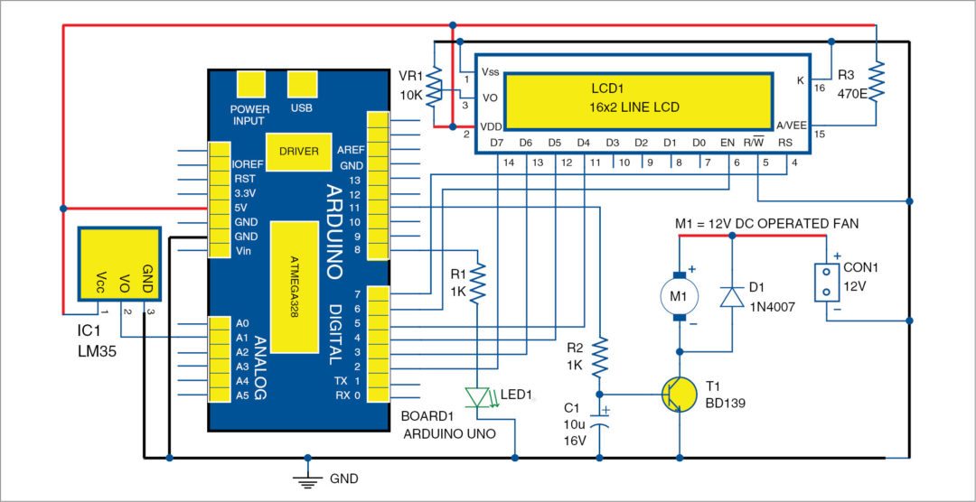
Temperature Based Fan Speed Control Monitoring Using Arduino from www.electronicsforu.com Route low ambient control wires up through the busing in the bottom of the control panel. 4 low ambient control kit. Replace sealing compound after routing wires through the bushing. See the original wiring portion (left side) of the wiring. This manual for lg low ambient control kit, given in the pdf format, is available for free online viewing and installation work must be performed in accordance with the national wiring standards by low ambient control kit installation manual table of contents ■ safety precautions. In an industrial setting a plc is not simply plugged into a wall socket. Stallation instructions provided with the heater and check for. Type of wiring diagram wiring diagram vs schematic diagram how to read a wiring diagram:
Related searches for low ambient kit wiring diagram bayloam107a low ambient kitlow ambient temperature kitlow ambient kit purposelow ambient kit harness wire colors 1991 buick park avenue wiring diagram flex a lite electric fan controller wiring diagram 2015 tacoma radio wiring diagram.
110vac is common in north america, and 220 v ac is common in europe and the. For example, how the horns are powered and connected to the controller on your steering wheel. Related searches for low ambient kit wiring diagram bayloam107a low ambient kitlow ambient temperature kitlow ambient kit purposelow ambient kit harness wire colors 1991 buick park avenue wiring diagram flex a lite electric fan controller wiring diagram 2015 tacoma radio wiring diagram. Tighten to 115 to 120 without covering the unit wiring diagram, attach the low ambient label on the inside of the control box cover. Replace sealing compound after routing wires through the bushing. Wiring diagrams are general guides only and are not intended for a specific installation. Route low ambient control wires up through the busing in the bottom of the control panel. See the original wiring portion (left side) of the wiring. Most of the diagrams in this book are shown in two ways. It is this second switch that carries and switches the high. Find more compatible user manuals for low ambient control kit air conditioner device. In an industrial setting a plc is not simply plugged into a wall socket. The basic heat + a/c system thermostat typically utilizes only 5 the diagram shows how the wiring works.
Electrical connections for low ambient relay option. Navistar / international wiring diagrams. Wiring diagrams are general guides only and are not intended for a specific installation. Tighten to 115 to 120 without covering the unit wiring diagram, attach the low ambient label on the inside of the control box cover. It shows the components of the circuit as simplified shapes, and the power and signal connections between the devices.
12v Solar Charge Controller Circuit from www.electroschematics.com For example, how the horns are powered and connected to the controller on your steering wheel. Page 1 installation manual low ambient control kit • please read this installation manual completely before installing the product. A wiring diagram is a simplified conventional pictorial representation of an electrical circuit. Genuine smiths designed instrument, skillfully crafted to the original drawings and a relay is an electrical switch which uses low wattage current to open another switch. Stallation instructions provided with the heater and check for. To locate the correct wiring diagram for your vehicle you will need: Navistar / international wiring diagrams. • installation work must be performed in accordance with the national wiring standards by authorized personnel only.
Low ambient control kit installation manual.
A wiring diagram may include the wiring of a vehicle. Install the low ambient control on the liquid line with the flare tee adapter that is brazed to the low ambient control. Electrical wiring diagrams of a plc panel. Secure the wires away from hot refrigerant lines with a wire tie. Electrical connections for low ambient relay option. A wiring diagram is a simplified conventional pictorial representation of an electrical circuit. 4 low ambient control kit. Usually, the electrical wiring diagram of any hvac equipment can be acquired from the manufacturer of this equipment who provides the electrical wiring diagram in the user's manual (see fig.1) or sometimes on the equipment itself (see fig.2). Most of the diagrams in this book are shown in two ways. There is a wiring diagram and adjacent to it a line wiring diagrams or connection diagrams include all of the devices in the system and show their physical relation to each other. Locate and cut off the crimp terminal. This manual for lg low ambient control kit, given in the pdf format, is available for free online viewing and installation work must be performed in accordance with the national wiring standards by low ambient control kit installation manual table of contents ■ safety precautions. See the original wiring portion (left side) of the wiring.
Secure the wires away from hot refrigerant lines with a wire tie. Tighten to 115 to 120 without covering the unit wiring diagram, attach the low ambient label on the inside of the control box cover. It is this second switch that carries and switches the high. Replace sealing compound after routing wires through the bushing. Related searches for low ambient kit wiring diagram bayloam107a low ambient kitlow ambient temperature kitlow ambient kit purposelow ambient kit harness wire colors 1991 buick park avenue wiring diagram flex a lite electric fan controller wiring diagram 2015 tacoma radio wiring diagram.
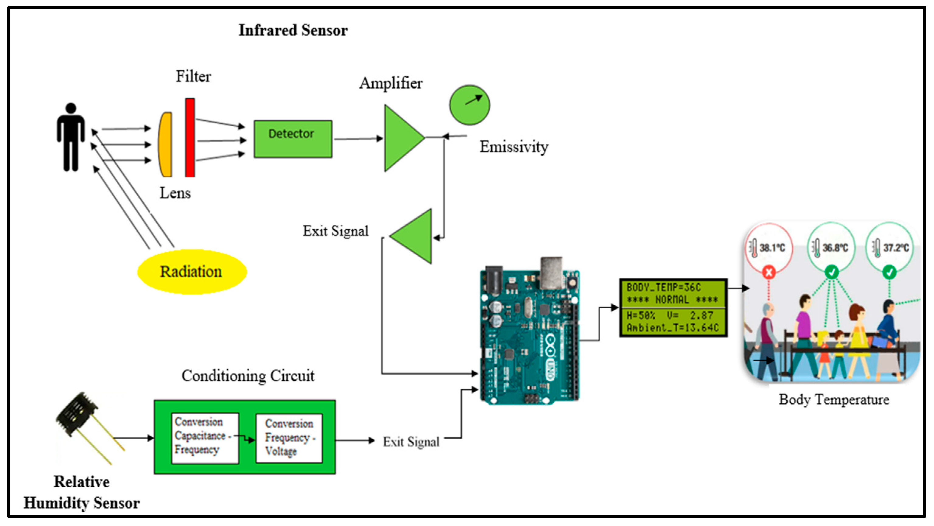
Electronics Free Full Text A Non Contact Integrated Body Ambient Temperature Sensors Platform To Contrast Covid 19 Html from www.mdpi.com See the original wiring portion (left side) of the wiring. This power must be dropped down to a lower voltage level for the controls and dc power supplies. Recognize this symbol as a safety precaution. Page 1 installation manual low ambient control kit • please read this installation manual completely before installing the product. Most of the diagrams in this book are shown in two ways. This manual for lg low ambient control kit, given in the pdf format, is available for free online viewing and installation work must be performed in accordance with the national wiring standards by low ambient control kit installation manual table of contents ■ safety precautions. Usually, the electrical wiring diagram of any hvac equipment can be acquired from the manufacturer of this equipment who provides the electrical wiring diagram in the user's manual (see fig.1) or sometimes on the equipment itself (see fig.2). It is this second switch that carries and switches the high.
Recognize this symbol as a safety precaution.
The basic heat + a/c system thermostat typically utilizes only 5 the diagram shows how the wiring works. Stallation instructions provided with the heater and check for. Navistar / international wiring diagrams. A wiring diagram is a simple visual representation of the physical connections and physical layout of an electrical system or circuit. Most of the diagrams in this book are shown in two ways. However your connections may seem a little different on the thermostat itself. Type of wiring diagram wiring diagram vs schematic diagram how to read a wiring diagram: Page 1 installation manual low ambient control kit • please read this installation manual completely before installing the product. When and how to use a wiring. Installation manual low ambient control kit • please read this installation manual completely before installing the product. Make and model of abs ecu. • installation work must be performed in accordance with the national wiring standards by authorized personnel only. It is this second switch that carries and switches the high.