Maxon Max Iii Wiring Diagram / Diagram Database Free Read Or Download Diagram Database : Position switch, clutch pedal, starting, no.. 600 x 630 png 139 кб. By katya marinon april 02, 2021in wiring diagram216 views. 3.3.5.2 digital input 2 input voltage max. Kymco agility city 50 wiring diagram. 24 vdc pin 4green gnd pin 5blue hall sensor 1 pin 6violet hall sensor 2 pin 7grey hall sensor 3 pin 8wiring diagram for hall sensors.
Maxon motor control escon servo controller escon 50/5 hardware reference. Which of the following structures of the mind is observable in the diagram below? It has to be admitted that autocad is common and standard when it comes to wiring diagrams. Maxon tpp480 portables ~ trunked type. Electrical circuit diagrams rave lr3 wiring pdfelectrical.
Https Www 4qte Com Pdf Maxongate Maxon Gpt Installation Pdf from Maxon motor control escon servo controller escon 50/5 hardware reference. Switch the power to off before disconnecting or connecting the power leads to the wiring panel. Set value (10 v or 3.9 v) and turn potentiometer p1 nmax until required max. Maxon datasheet, maxon pdf, maxon data sheet, maxon manual, maxon pdf, maxon, datenblatt, electronics maxon, alldatasheet, free, datasheet, datasheets, data sheet, datas sheets maxon datasheet, pdf. Csi maxon radiotelemetry network table of contents this is a blank page. The max point reward for answering a question is 15. Quickly design professional and accurate wiring diagram with edrawmax. 24 vdc pin 4green gnd pin 5blue hall sensor 1 pin 6violet hall sensor 2 pin 7grey hall sensor 3 pin 8wiring diagram for hall sensors.
Kymco agility city 50 wiring diagram.
Maxon schematic electric guitar canadian quartet modasaurus display expert musicianship in a session firmly rooted in contemporary jazz fusion despite its general popularity the enormous. Power and control circuit for 3 phase two speed motor. Input voltage logic 0 logic 1. Electrical circuit diagrams rave lr3 wiring pdfelectrical. Maxon motor control escon servo controller escon 50/5 hardware reference. Rights reserved in the event of the grant of a patent, utility model or. Signal sequence diagram for the hall sensors. Wire diagram−conventional, 12v mack, 2013bp. Quickly design professional and accurate wiring diagram with edrawmax. Maxon motor 230572 maxon dc motor 24v maxon brushless ec motor driver maxon ec motor maxon maxon motor ec max 22 maxon dc motor ec 45 hall effect sensor 521 text: Switch the power to off before disconnecting or connecting the power leads to the wiring panel. Maxon liftgate wiring diagram maxon liftgate wiring diagram. Conductive phases i ii iii iv v vi sensorless commutation rotor position 60 120 180 240 300 360 1 hall sensor 1 0 1 emf hall sensor 2 0 1 hall sensor 3 0 legend supplied motor.
By katya marinon april 02, 2021in wiring diagram216 views. Signal sequence diagram for the hall sensors. Power and control circuit for 3 phase two speed motor. Make sure that bends in the electrical wiring are 1. Comply with all warning and instruction decals attached to the liftgate.
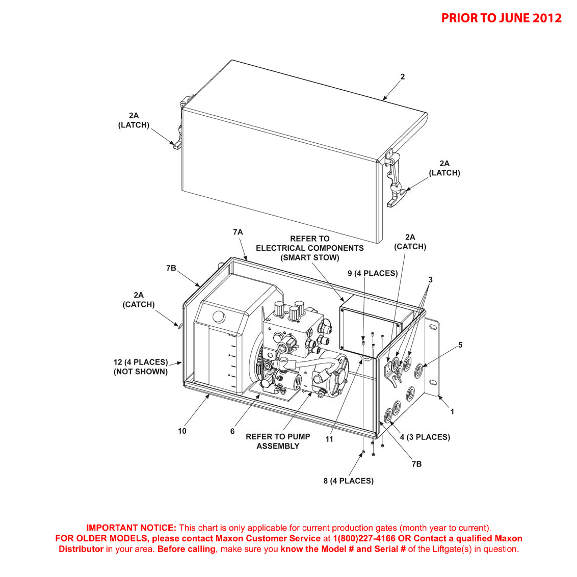
Your Guide To Maxon Liftgate Parts And New Gates Liftgateme from cdn.shopify.com Csi maxon radiotelemetry network table of contents this is a blank page. Lr3 wiring diagram diagram data pre. It has to be admitted that autocad is common and standard when it comes to wiring diagrams. 1000 feet maximum to optional remote user display eia level 4 cable, 2 twisted pair with shield, 22. View online(73 pages) or download pdf(3.34 mb) maxon bmrsd installation manual • bmrsd tractor 12(max. Detroit diesel ddec iv series 60 my2003 egr engine sensor harness wiring diagram.png. By katya marinon april 02, 2021in wiring diagram216 views. 24 vdc pin 4green gnd pin 5blue hall sensor 1 pin 6violet hall sensor 2 pin 7grey hall sensor 3 pin 8wiring diagram for hall sensors.
24 vdc pin 4green gnd pin 5blue hall sensor 1 pin 6violet hall sensor 2 pin 7grey hall sensor 3 pin 8wiring diagram for hall sensors.
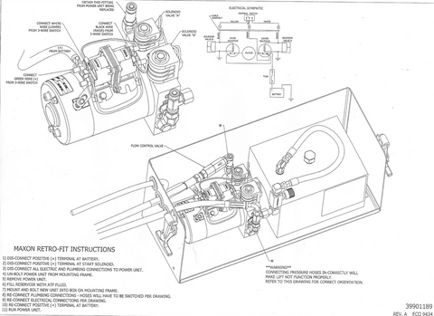
Input voltage logic 0 logic 1. Comply with all warning and instruction decals attached to the liftgate. Maxon datasheet, maxon pdf, maxon data sheet, maxon manual, maxon pdf, maxon, datenblatt, electronics maxon, alldatasheet, free, datasheet, datasheets, data sheet, datas sheets maxon datasheet, pdf. Determine and define of wires. 100 feet max length to each actuator; Wiring diagram for two speed moto explained. Switch the power to off before disconnecting or connecting the power leads to the wiring panel. Maxon max iii wiring diagram. 4 ma max 4 ma max 4 ma max. View online(73 pages) or download pdf(3.34 mb) maxon bmrsd installation manual • bmrsd tractor 12(max. 3.3.5.2 digital input 2 input voltage max. 1000 feet maximum to optional remote user display eia level 4 cable, 2 twisted pair with shield, 22. Electrical circuit diagrams rave lr3 wiring pdfelectrical.
Wire diagram−conventional, 12v mack, 2013bp. Dahlender winding.like, subscribe and don't skip the. Provides general information and wiring diagrams for the i/o modules. Wiring diagram for two speed moto explained. Maxon schematic electric guitar canadian quartet modasaurus display expert musicianship in a session firmly rooted in contemporary jazz fusion despite its general popularity the enormous.
Maxon Slidelift Gpslr Liftgates Parts And Diagrams Shop Ite Parts from iteparts.com Maxon motor 230572 maxon dc motor 24v maxon brushless ec motor driver maxon ec motor maxon maxon motor ec max 22 maxon dc motor ec 45 hall effect sensor 521 text: Make sure that bends in the electrical wiring are 1. Always route electrical wires clear of moving parts, brake lines, sharp edges and system diagrams. Epos2 24/2 for maxon dc motors (390438); Wiring diagram for two speed moto explained. Lr3 wiring diagram diagram data pre. Dahlender winding.like, subscribe and don't skip the. Conductive phases i ii iii iv v vi sensorless commutation rotor position 60 120 180 240 300 360 1 hall sensor 1 0 1 emf hall sensor 2 0 1 hall sensor 3 0 legend supplied motor.
Quickly design professional and accurate wiring diagram with edrawmax.
Maxon liftgate wiring diagram maxon liftgate wiring diagram. Quickly design professional and accurate wiring diagram with edrawmax. Detroit diesel ddec ii and iii wiring diagrams.pdf. Maxon max iii wiring diagram. Make sure that bends in the electrical wiring are 1. Provides general information and wiring diagrams for the i/o modules. Csi maxon radiotelemetry network table of contents this is a blank page. 100 feet max length to each actuator; 4 ma max 4 ma max 4 ma max. Comply with all warning and instruction decals attached to the liftgate. 600 x 630 png 139 кб. 1000 feet maximum to optional remote user display eia level 4 cable, 2 twisted pair with shield, 22. Set value (10 v or 3.9 v) and turn potentiometer p1 nmax until required max.