Home
› Trailer Brake Control Wiring Diagram / 31 Prodigy P2 Brake Controller Wiring Diagram Wiring Diagram Database / When you make use of your finger or perhaps follow the circuit with your eyes, it may be easy to mistrace the circuit.
Trailer Brake Control Wiring Diagram / 31 Prodigy P2 Brake Controller Wiring Diagram Wiring Diagram Database / When you make use of your finger or perhaps follow the circuit with your eyes, it may be easy to mistrace the circuit.
Trailer Brake Control Wiring Diagram / 31 Prodigy P2 Brake Controller Wiring Diagram Wiring Diagram Database / When you make use of your finger or perhaps follow the circuit with your eyes, it may be easy to mistrace the circuit.. Dexter, tap / hopkins, tekonsha and drawtite. Wiring guides ford trailer brake control hopkins controller diagram for box f250 7 pole and 4 37185 breakaway impulse 47235. Ensure it is sealed off and cannot create a short circuit with any other wire or the chassis. Important facts to remember 1. Please locate it before you proceed.
Trailer wiring connectors various connectors are available from four to seven pins that allow for the transfer of power for the lighting as well as auxiliary functions such as an electric trailer brake controller, backup lights, or a 12v power supply for a winch or interior trailer lights. A wiring diagram is a streamlined conventional pictorial representation of an electric circuit. How to install a trailer brake controller on a gm van without a quick connect plug. Shop over 2 million products at zoro.com! As the name implies, they use four wires to carry out the vital lighting functions.
Trailer Brake Controller Operation from www.needatrailer.com Of transportation requires that trailers equipped with brakes have a trailer break away system for activation of the trailer brakes, in the event that the trailer should become detached from the tow vehicle during highway travel. The image above shows a single axle trailer, and the next image shows wiring for tandem axles. Read and follow all instructions carefully before wiring brake control. Collection of ford trailer brake controller wiring diagram. A brake controller wiring installation kit makes light work! Wiring diagram also offers beneficial suggestions for tasks that may require some added tools. Failure to do so could result in damage to the brake control unit, no trailer brakes or poor brake performance. The brake control must be installed with a 12 volt negative ground system.
How to install a trailer brake controller on a gm van without a quick connect plug.
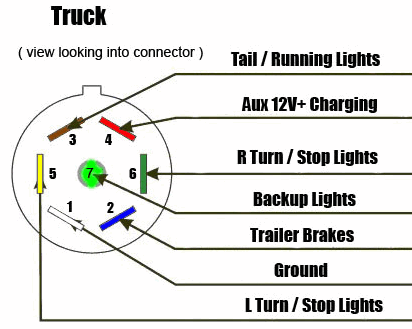
It will likely be in a position to offer you. Keep these instructions with the brake control for future reference. Disconnect the electrical plug between the trailer and tow vehicle before testing a breakaway switch. The brake control must be installed with a 12 volt negative ground system. Read and follow all instructions carefully before wiring brake control. This book even consists of suggestions for additional materials that you may want as a way to finish your assignments. White pin for the ground. As the name implies, they use four wires to carry out the vital lighting functions. They also provide a wire for a ground connection. Assortment of electric trailer brake wiring schematic. Trailer brake control wiring diagram. The four wires control the turn signals, brake lights and taillights or running lights. Ford trailer brake controller wiring diagram from www.ranger5g.com print the electrical wiring diagram off in addition to use highlighters to trace the signal.
How to install a trailer brake controller on a gm van without a quick connect plug. Trailer parts superstore® sells a wide selection of electronic trailer brake controllers from some of the industries most respected manufacturer's: Shop over 2 million products at zoro.com! Following the wiring diagram included with the controller, run the blue wire through the firewall and to the rear of the vehicle where it will connect to the trailer connector. Duplex wire, 20 amp circuit breaker and attaching terminals.
Tekonsha Brake Controller Wiring Diagram from i0.wp.com Warning reversing black and white wires or improper wiring will damage or destroy brake control. I have the original ford plug and wirers. The brake control must be installed with a 12 volt negative ground system. This voyager trailer brake controller wiring diagram model is much more suitable for sophisticated trailers and rvs. It reveals the parts of the circuit as streamlined forms, as well as the power and signal connections in between the gadgets. Contact technical service for periodic. Wiring kit for 2 to 4 brake control systems, includes 25 ft. I just don't know what the brown wire is.
Keep these instructions with the brake control for future reference.
Free shipping on orders > $50. It's pretty easy.get the activator ii here: If you would like to give some information about your vehicle, i could make a more specific recommendation on how to wire it and let you know if any other parts are needed. Joined sep 1, 2011 · 107 posts. A wiring diagram is a streamlined conventional pictorial depiction of an electric circuit. Only the (blue) brake and (white) ground wires are different. Trailer wiring connectors various connectors are available from four to seven pins that allow for the transfer of power for the lighting as well as auxiliary functions such as an electric trailer brake controller, backup lights, or a 12v power supply for a winch or interior trailer lights. Disconnect the electrical plug between the trailer and tow vehicle before testing a breakaway switch. $ wiring kit for 6 to 8 brake control. Collection of ford trailer brake controller wiring diagram. Warning reversing black and white wires or improper wiring will damage or destroy brake control. This voyager trailer brake controller wiring diagram model is much more suitable for sophisticated trailers and rvs. Typical trailer wiring diagram and schematic these 2 wire diagrams fit the needs of most trailers.
Collection of ford trailer brake controller wiring diagram. Contact technical service for periodic. Free shipping on orders > $50. This voyager trailer brake controller wiring diagram model is much more suitable for sophisticated trailers and rvs. White pin to your ground.
7 Way Diagram Aj S Truck Trailer Center from www.ajtnt.com November 19, 2020 1 margaret byrd. Trailer brake control wiring diagram. The brake control must be installed with a 12 volt negative ground system. Wiring diagram also offers beneficial suggestions for tasks that may require some added tools. $ wiring kit for 6 to 8 brake control. The service brake circuit must be disconnected from an existing trailer plug. Trailer wiring connectors various connectors are available from four to seven pins that allow for the transfer of power for the lighting as well as auxiliary functions such as an electric trailer brake controller, backup lights, or a 12v power supply for a winch or interior trailer lights. Trailer parts superstore® sells a wide selection of electronic trailer brake controllers from some of the industries most respected manufacturer's:
Trailer parts superstore® sells a wide selection of electronic trailer brake controllers from some of the industries most respected manufacturer's:
Free shipping on orders > $50. Wiring guides ford trailer brake control hopkins controller diagram for box f250 7 pole and 4 37185 breakaway impulse 47235. I have the original ford plug and wirers. The image above shows a single axle trailer, and the next image shows wiring for tandem axles. Ford trailer brake controller wiring diagram from www.ranger5g.com print the electrical wiring diagram off in addition to use highlighters to trace the signal. A wiring diagram is a streamlined conventional pictorial representation of an electric circuit. Trailer brake controllers and vehicle wiring. Trailer wiring connectors various connectors are available from four to seven pins that allow for the transfer of power for the lighting as well as auxiliary functions such as an electric trailer brake controller, backup lights, or a 12v power supply for a winch or interior trailer lights. It reveals the parts of the circuit as streamlined forms, as well as the power and signal connections in between the gadgets. Wiring instructions for electronic brake controls p/n 4399 rev k generic wiring diagram read this first: As the name implies, they use four wires to carry out the vital lighting functions. Keep these instructions with the brake control for future reference. Hopkins trailer brake control wiring diagram.