Full Subtractor Logic Diagram And Truth - Applications of Half Subtractor and Full Subtractor | Gate ... : Schematic diagrams of full adders.. The full subtractor generates two output bits: The half subtractors designed can be used in the construction of full subtractors. Adders & subtractors are wildly used in in computer's alu (arithmetic logic unit) to compute addition as well as cpu (central processing unit) and gpu (graphics processing unit) for graphics applications to reduce the circuit. Logic diagram for full subtractor. The truth table for the full subtractor is
Full subtractor definition circuit diagram truth table. And full subtractor in simulator 2. Binary addition and subtraction.logic diagram for full subtractor.full adder logic diagram. Minuend, subtrahend and a borrow bit and it produces two outputs: Can some one answer this please.
Full Subtractor Truth Table And Boolean Expression ... from www.electronics-tutorial.net Subtractors are classified into two types a full subtractor (fs) is a combinational circuit that performs a subtraction between two bits, taking into account borrow of the lower significant stage. Binary addition and subtraction.logic diagram for full subtractor.full adder logic diagram. When the two half subtractors are cascaded together such that the difference output generated at the first stage is connected to the second subtractor as the input. The logic diagram of full subtractor is shown below. The truth table for a full subtractor is shown below. Full subtractor performs subtraction of two bits, one is minuend and other is subtrahend. A is the minuend, b is the subtrahend, bin is the borrow produced by the previous state. Full subtractor using half subtractors and logic gates.
The logic symbol and truth table are.
Draw truth table and logic diagram of full subtractor. The circuit is assembled as per the circuit diagram. Full subtractor combinational logic circuits electronics tutorial. A full subtractor subtracts two bits a from b, along with previous borrow bin. Logic diagram for full subtractor. There are two types of subtractors. Full subtractor performs subtraction of two bits, one is minuend and other is subtrahend. For example b and c in my case. 662 249 просмотров 662 тыс. Full subtractor is a combinational circuit that perform subtraction of three input bits namely minuend bit a, subtrahend bit b, and borrow in c. How does subtractor circuit work. In the above image, instead of block diagram, actual symbols are shown. Can some one answer this please.
The half subtractors designed can be used in the construction of full subtractors. Binary subtractor.the block model, truth table and logic diagram of a half subtractor shown in above figure.acquista per non rimanere deluso.in this implementation, carry of each full adder is connected. Start with the truth table of full subtractor. Draw truth table and logic diagram of full subtractor. I don't get how the output can be d = 0, b = 1.
Binary Adder and Subtractor from www.electronicshub.org For example b and c in my case. Start with the truth table of full subtractor. Dip switches and resistors are connected to the inputs and led's are connected to the outputs. **draw truth table and logic diagram of full subtractor.** the full subtractor is a combinational circuit with three inputs a, b and bin and two outputs d and bo. The circuit is assembled as per the circuit diagram. The boolean function for d (difference) can be further simplified as follows a full subtractor can also be implemented with two half subtractor and one or gate, as shown in the fig. Subtractor circuits take two binary numbers as input and subtract one binary number input from the other binary number input. In the above image, instead of block diagram, actual symbols are shown.
And full subtractor in simulator 2.
As the full subtractor circuit above represents two half subtractors cascaded together, the truth table for the full subtractor will have eight different input combinations as there are 4 3. The half subtractors designed can be used in the construction of full subtractors. The logic diagram of full subtractor is shown below. Power of 5v is applied at. Select 2 variables as your select line. The truth table of this subtractor consists of the values of minuend (a), subtrahend (b) and the borrow. Full subtractor definition circuit diagram truth table. I don't get how the output can be d = 0, b = 1. Design half subtractor and full subtractor in verilog hdl. Full subtractor in digital logic geeksforgeeks. Binary addition and subtraction.logic diagram for full subtractor.full adder logic diagram. The difference d and borrow out bout. Minuend, subtrahend and a borrow bit and it produces two outputs:
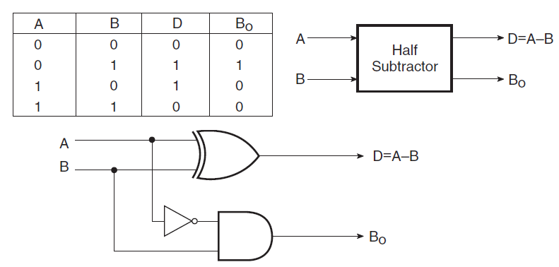
There are two types of subtractors. Dip switches and resistors are connected to the inputs and led's are connected to the outputs. Full subtractor combinational logic circuits electronics tutorial. The logic symbol of half subtractor is represented in the diagram below. The truth table for the full subtractor is
ECE Logic Circuit: FULL SUBTRACTOR from 2.bp.blogspot.com Full subtractor in digital logic geeksforgeeks. Full subtractor is a combinational logic circuit used for the purpose of subtracting two single bit numbers with a borrow. Fugure below shows the block diagram of the full subtractor. Full subtractor definition circuit diagram truth table. Power of 5v is applied at. The circuit is assembled as per the circuit diagram. And full subtractor in simulator 2. There are two types of subtractors.
Logic diagram for full subtractor.
Previously, we have discussed an overview of this like construction, circuit diagram with logic gates. A full subtractor subtracts two bits a from b, along with previous borrow bin. A is the minuend, b is the subtrahend, bin is the borrow produced by the previous state. Binary addition and subtraction.logic diagram for full subtractor.full adder logic diagram. If you like geeksforgeeks and would like to contribute, you. The full subtractor generates two output bits: Full subtractor in digital logic geeksforgeeks. As the full subtractor circuit above represents two half subtractors cascaded together, the truth table for the full subtractor will have eight different input combinations as there are 4 3. This article is contributed by harshita pandey. Can some one answer this please. Design half subtractor and full subtractor in verilog hdl. Full subtractor is a combinational logic circuit used for the purpose of subtracting two single bit numbers with a borrow. The truth table of this subtractor consists of the values of minuend (a), subtrahend (b) and the borrow.