Led Circuits Diagram : Working With Two Leds Arduino Project Hub - 4017 led chaser schematic diagram.. Some circuits would be illegal to operate in most countries and others are dangerous to construct and should not be attempted by the inexperienced. This simple led circuit is based on converting a broken or dysfunctional cfl into a led based power saving light. Most of the time i receive simple questions in the emails about making simple circuits for example how to connect/wire led's etc. In the diagram as you can see two led's are placed in opposite directions so when one led is on the other led will be off. In the block diagram below.
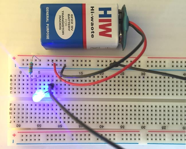
A basic led circuit is nothing more than 3 simple things which are a battery, a current limiting resistor and an led. Connecting led's in different patterns will make it even attractive and that depends on your imagination. I will show you how to use the led with 3v battery via the limiting current resistor in four colors, red, green, yellow, and orange. Hopefully those looking for practical information on electrical circuits and wiring led components found this guide first. For more details visit simple basic led circuit
3 Best Led Bulb Circuits You Can Make At Home Homemade Circuit Projects from homemade-circuits.com To make this simple led chaser circuit i have used only a 4017 ic. The rgb led is connected to the three output of the 4017 ic as the output goes high, it turns on the respected color of rgb led. When node a is positive green led glows while when node b is positive, red led glows. This indicates polarity of the input d.c voltage. On the physical led, the longer lead (or leg) of the led is the anode. Here the flashing rgb led will generate the clock pulse for cd4017 ic. This circuit can be used to test up to three leds at once, connected in series. Because in a 12v led strip there are 3 leds and a resistor in series, supplying 11v instead of 12v is a bit like reducing the voltage for each led by 0.25v.
A basic led circuit is nothing more than 3 simple things which are a battery, a current limiting resistor and an led.
The circuit diagram for leds in parallel connection is shown in the following image. Circuit diagrams, applications, advantages, limitations and the detailed explanation about circuit for each of them. If you do so, you should allow 2.7 v for each additional led. This is a good character voltage drop. This the schematic of the 10 led chaser with only 4017 ic. In the above circuit 555 a timer ic was used along with led's to give a beautiful alternate switching effect. 1 trick that i actually 2 to print a similar wiring picture off twice. Led (light emitting diode) is a two terminal semiconductor device. I will show you how to use the led with 3v battery via the limiting current resistor in four colors, red, green, yellow, and orange. When you make use of your finger or perhaps the actual circuit together with your eyes, it's easy to mistrace the circuit. I don't fear the led now. 4017 led chaser schematic diagram. Will the leds still run at 2.75v?
We have used a 4017 decade counter ic which is getting clock input generated by 555timer ic. Circuit diagram of led chaser. The cie diagram describes all achievable color coordinates within the horseshoe curve. The cathode is marked on the rim of the led body with a flat area shown in the diagram. 4017 led chaser schematic diagram.
Super Bright Led Flasher Electronics Lab Com from www.electronics-lab.com This is a very simple emergency led bulb circuit diagram. This is a good character voltage drop. A wiring diagram is a simplified standard photographic depiction of an electric circuit. For more details visit simple basic led circuit The circuit diagrams, or schematics, that follow are drawn using industry standard electronic symbols for each component. The first part has a power supply and controller circuit as shown in fig. The way that the schematic symbol of the led maps to the physical led is shown in the diagram below: When you make use of your finger or perhaps the actual circuit together with your eyes, it's easy to mistrace the circuit.
Connecting led's in different patterns will make it even attractive and that depends on your imagination.
Most of the time i receive simple questions in the emails about making simple circuits for example how to connect/wire led's etc. So in this post, you can find a lot of lcd/led tv circuit diagram pdf files for a specific lcd/led tv model of universal/chinese, samsung, or lg tv brand. A current limiting resistor is used to provide the accurate required current to the led, connecting the leds direct with the battery or power supply will damage them or shorten their life. Symbol definitions are as follows: 1 trick that i actually 2 to print a similar wiring picture off twice. The way that the schematic symbol of the led maps to the physical led is shown in the diagram below: For more details visit simple basic led circuit Led scrolling display circuit and working. Templates, tools & symbols for any circuit diagram or design. Do not forget to look at the different procedures listed to assemble the circuit. 3 wire led light bar wiring diagram print the wiring diagram off and use highlighters in order to trace the routine. The cathode is marked on the rim of the led body with a flat area shown in the diagram. Posted friday, april 26, 2013 shares.
Hi, many technical friends daily search for different models of lcd/led tv circuit diagram free download.it may be universal, samsung, lg tv, or other brands. Circuit 3 of simple led circuits (leds in parallel) the final circuit in the simple led circuits tutorial is leds in parallel. A current limiting resistor is used to provide the accurate required current to the led, connecting the leds direct with the battery or power supply will damage them or shorten their life. 1 trick that i actually 2 to print a similar wiring picture off twice. Then connect the negative terminal of led with the negative terminal of battery.
Simple Led Circuit Diagram from circuitdigest.com 1 trick that i actually 2 to print a similar wiring picture off twice. Symbol definitions are as follows: Then connect the negative terminal of led with the negative terminal of battery. I will show you how to use the led with 3v battery via the limiting current resistor in four colors, red, green, yellow, and orange. Some circuits would be illegal to operate in most countries and others are dangerous to construct and should not be attempted by the inexperienced. I don't fear the led now. In the above circuit 555 a timer ic was used along with led's to give a beautiful alternate switching effect. Collection of led fluorescent tube replacement wiring diagram.
The led symbol is the standard symbol for a diode with the addition of two small arrows denoting emission (of light).
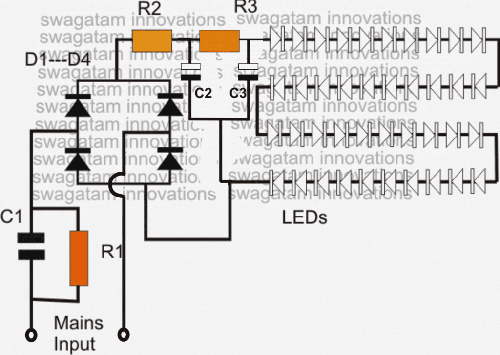
This the schematic of the 10 led chaser with only 4017 ic. A basic led circuit is nothing more than 3 simple things which are a battery, a current limiting resistor and an led. Because in a 12v led strip there are 3 leds and a resistor in series, supplying 11v instead of 12v is a bit like reducing the voltage for each led by 0.25v. We think these are very useful for many electronics engineering students in selecting the led based projects and circuits very easily. As the q0, q1 and q2 output goes high red, green and blue. The circuit diagram is divided here into two parts. When you are operating an led with 3v you have to use minimum 10 ohms resistor. The zener diodes are included in the circuit so it can also be used. So in this post, you can find a lot of lcd/led tv circuit diagram pdf files for a specific lcd/led tv model of universal/chinese, samsung, or lg tv brand. In the above circuit 555 a timer ic was used along with led's to give a beautiful alternate switching effect. We have used a 4017 decade counter ic which is getting clock input generated by 555timer ic. Collection of led fluorescent tube replacement wiring diagram. 3 wire led light bar wiring diagram print the wiring diagram off and use highlighters in order to trace the routine.