Home
› Lighting Control Panel Wiring Diagram - What Is Electrical Interlocking Power Control Diagrams - Assortment of crestron lighting control wiring diagram.
Lighting Control Panel Wiring Diagram - What Is Electrical Interlocking Power Control Diagrams - Assortment of crestron lighting control wiring diagram.
Lighting Control Panel Wiring Diagram - What Is Electrical Interlocking Power Control Diagrams - Assortment of crestron lighting control wiring diagram.. The most common form of lighting control today is a single switch or dimmer controlling a light or group of lights (a zone of lighting). Wiring the lighting control panel is made of stainless steel, and has knockouts on the top and bottom of the panel. To ensure optimum performance over the full range of the installation topology, use crestron certified wire. Relays to be purchased separately and to be installed in the field by a certified electrician. The panels activate thelighting through automatic scenarios, time schedules, photocells and occupancy controlled switches.
Electrical wiring diagrams of a plc panel in an industrial setting a plc is not simply plugged into a wall socket. Troubleshooting a blinking green relay board status led indicates that communication has not been properly established for this No software installation is required. It shows the parts of the circuit as simplified shapes, and also the power as well as signal connections between the tools. The most common form of lighting control today is a single switch or dimmer controlling a light or group of lights (a zone of lighting).
Ay 2569 Hayward Heat Pump Schematic Free Download Wiring Diagram Schematic Download Diagram from static-assets.imageservice.cloud However, a network connection to the area controller is required for programming the panel. The panel is now fully functional and ready to control the lighting loads. Troubleshooting a blinking green relay board status led indicates that communication has not been properly established for this Lcp u lighting control panel is a rugged nema1 grade panel made of 16 ga steel with a white powder coat finish used to simplify the design and installation of pulseworx dimmers. Pdf wet location touch switch input module (wd0401) wiring diagrams Variety of electrical control panel wiring diagram. • relays are mounted with lighting circuit terminals in the high voltage area. The easy to use setup tool, scenarios menu, makes project commissioning simple and fast.
Pdf apprentice 3 panel (wd0003) wiring diagrams :
The nx™ lighting control panel is designed to operate as part of a nx networked lighting control system. Pdf wet location touch switch input module (wd0401) wiring diagrams Electrical wiring diagrams of a plc panel in an industrial setting a plc is not simply plugged into a wall socket. It shows the parts of the circuit as simplified shapes, and also the power as well as signal connections between the tools. Each page of this wiring diagram shows the exact wiring for different sections of this control panel. To ensure optimum performance over the full range of the installation topology, use crestron certified wire. Gain the competitive edge that lutron has enjoyed for more than 50 years through light control education and training. Main lighting power the panel can contain contactors and/or terminals to control external contactors. • relays are mounted with lighting circuit terminals in the high voltage area. Lighting control panel 16 and 24 installation instructions panel notes • cx panels are manufactured fully populated with relays or empty without relays. It reveals the elements of the circuit as simplified forms, and also the power and also signal connections in between the tools. Ø1/4 mounting holes at 4 places (hardware not included). The kameleon k4lighting control system series are a relay based automatic lighting control panel system designed to meet the requirements of any commercial or industrial applications.
Within a typical nlight network, multiple zones are wired individually to a bridge. It shows the parts of the circuit as simplified shapes, and also the power as well as signal connections between the tools. Acuity brands provides a comprehensive selection of lighting control panels. This is what we draw using autocad electrical. Pdf apprentice 3 panel (wd0003) wiring diagrams :
Control Panel Wiring Diagram Pdf from i0.wp.com The panel is now fully functional and ready to control the lighting loads. Pdf apprentice 3 panel (wd0003) wiring diagrams : Wiring the lighting control panel is made of stainless steel, and has knockouts on the top and bottom of the panel. Failure to do so may incur additional charges if Hinged door panel provides a barrier between control interface and high voltage connections beneath (master only). The most common form of lighting control today is a single switch or dimmer controlling a light or group of lights (a zone of lighting). This is what we draw using autocad electrical. Main lighting power the panel can contain contactors and/or terminals to control external contactors.
A wiring diagram is a simplified traditional photographic depiction of an electrical circuit.
Think of the time and effort expended turning the lights on in A new dawn in lighting controls. Relays to be purchased separately and to be installed in the field by a certified electrician. No software installation is required. Once programmed, the panel will operate independently from a network connection. Pdf wet location touch switch input module (wd0401) wiring diagrams This is what we draw using autocad electrical. In this section, find industry primers, online tools, training seminars, exhibits, and more. While this historic standard certainly works, it is cumbersome relative to the ease of a lighting control system, especially in larger homes. Variety of lighting control panel wiring diagram. Troubleshooting a blinking green relay board status led indicates that communication has not been properly established for this Each page of this wiring diagram shows the exact wiring for different sections of this control panel. All the wiring that you see in the panel is done based on the wiring diagram.
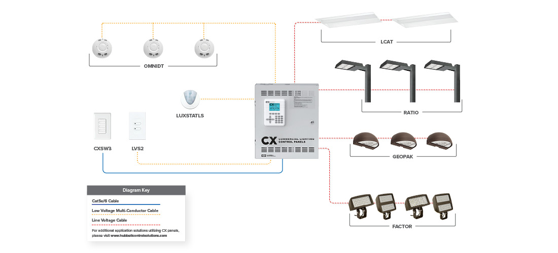
Lighting control panel 16 and 24 installation instructions panel notes • cx panels are manufactured fully populated with relays or empty without relays. The panel is now fully functional and ready to control the lighting loads. All the wiring that you see in the panel is done based on the wiring diagram. From there, the switched/dimmed circuits are routed directly to the loads (see figure 2). It reveals the elements of the circuit as simplified forms, and also the power and also signal connections in between the tools.
Cx Commercial Lighting Control Panels System Hubbell Control Solutions from hubbellcdn.com The most common form of lighting control today is a single switch or dimmer controlling a light or group of lights (a zone of lighting). Electrical wiring diagrams of a plc panel in an industrial setting a plc is not simply plugged into a wall socket. For instance, for our emergency stop push button, it shows the wiring for this switch. The kameleon k4lighting control system series are a relay based automatic lighting control panel system designed to meet the requirements of any commercial or industrial applications. Variety of electrical control panel wiring diagram. Once programmed, the panel will operate independently from a network connection. From there, the switched/dimmed circuits are routed directly to the loads (see figure 2). Lcp u lighting control panel is a rugged nema1 grade panel made of 16 ga steel with a white powder coat finish used to simplify the design and installation of pulseworx dimmers.
Control power 120v ac control power must be supplied to terminal h1 and a neutral to n1 from a maximum 20a breaker.
Ø1/4 mounting holes at 4 places (hardware not included). The nx™ lighting control panel is designed to operate as part of a nx networked lighting control system. From there, the switched/dimmed circuits are routed directly to the loads (see figure 2). The lcd user interface is located on the door and utilizes simple and intuitive scrolling menus to program, check status or update the panel. However, a network connection to the area controller is required for programming the panel. Once programmed, the panel will operate independently from a network connection. In this section, find industry primers, online tools, training seminars, exhibits, and more. All the wiring that you see in the panel is done based on the wiring diagram. • relays are mounted with lighting circuit terminals in the high voltage area. It reveals the elements of the circuit as simplified forms, and also the power and also signal connections in between the tools. Electrical wiring diagrams of a plc panel in an industrial setting a plc is not simply plugged into a wall socket. A wiring diagram is a simplified standard pictorial depiction of an electric circuit. Acuity brands provides a comprehensive selection of lighting control panels.